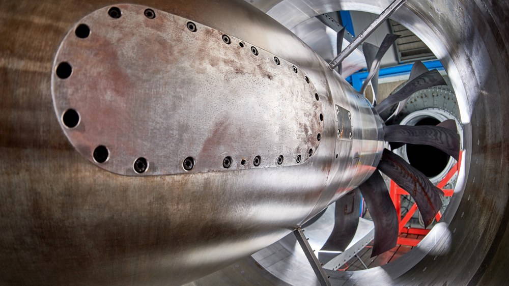
The compressor test rig enables a wide range of compressor investigations to be carried out, from measuring the complete compressor map, determining the surge limit using detailed flow field measurements, to special applications such as active noise control on single-stage fans or counter-rotating propfans.
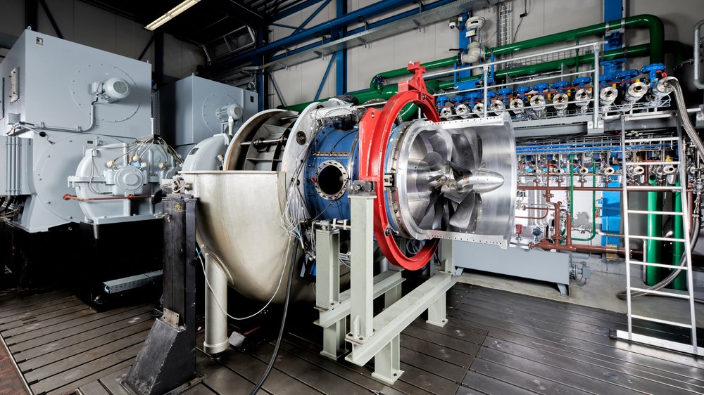
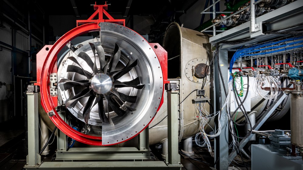
The multi-stage twin-shaft axial compressor test rig is available for experimental research on axial machines. Not only can single or multi-stage compressors be investigated, but also counter-rotating compressors, fans and combinations of low and high pressure compressors at different speeds.
The power unit consists of two electric motors driving two concentric shafts of the compressor test rig via a gearbox combination. The speeds of the two motors can be adjusted independently and continuously from 0 to 2000 rpm and the direction of rotation can be selected as required. A simple coupling mechanism on the hollow core shaft system also allows both motors to act on a single shaft train. The power of the motors is 5 MW each at nominal speed, giving up to 10 MW in coupled operation. Depending on the combination of gear sets in the gearboxes, output speeds of up to 20,200 rpm can be achieved.
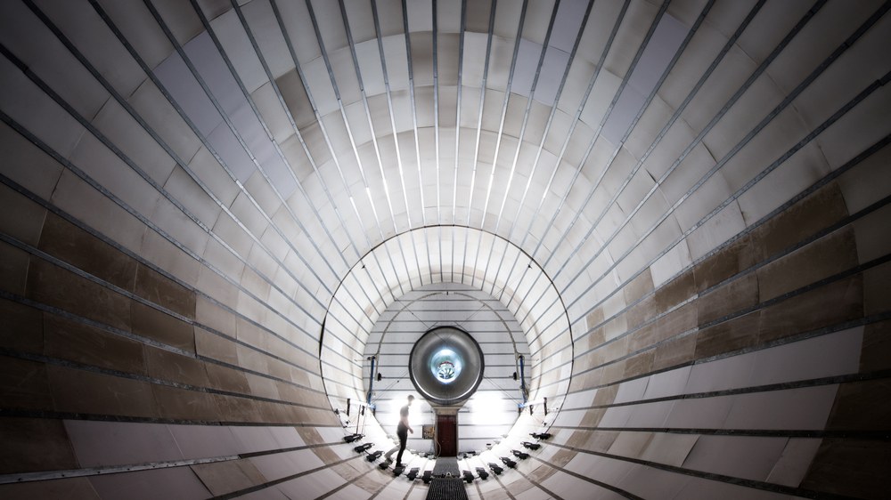
The air is drawn in from the atmosphere via the inlet tower and, after being deflected through 90°, enters the stabilisation chamber. If required, an inlet throttle can be installed to reduce the total pressure, for example to reduce the power consumption of the test compressor. The air enters the test compressor through a nozzle. A maximum mass flow of 160 kg/s can be achieved.
Multistage twin-shaft axial compressor test bench at the Institute of Propulsion Technology with CRISP rig
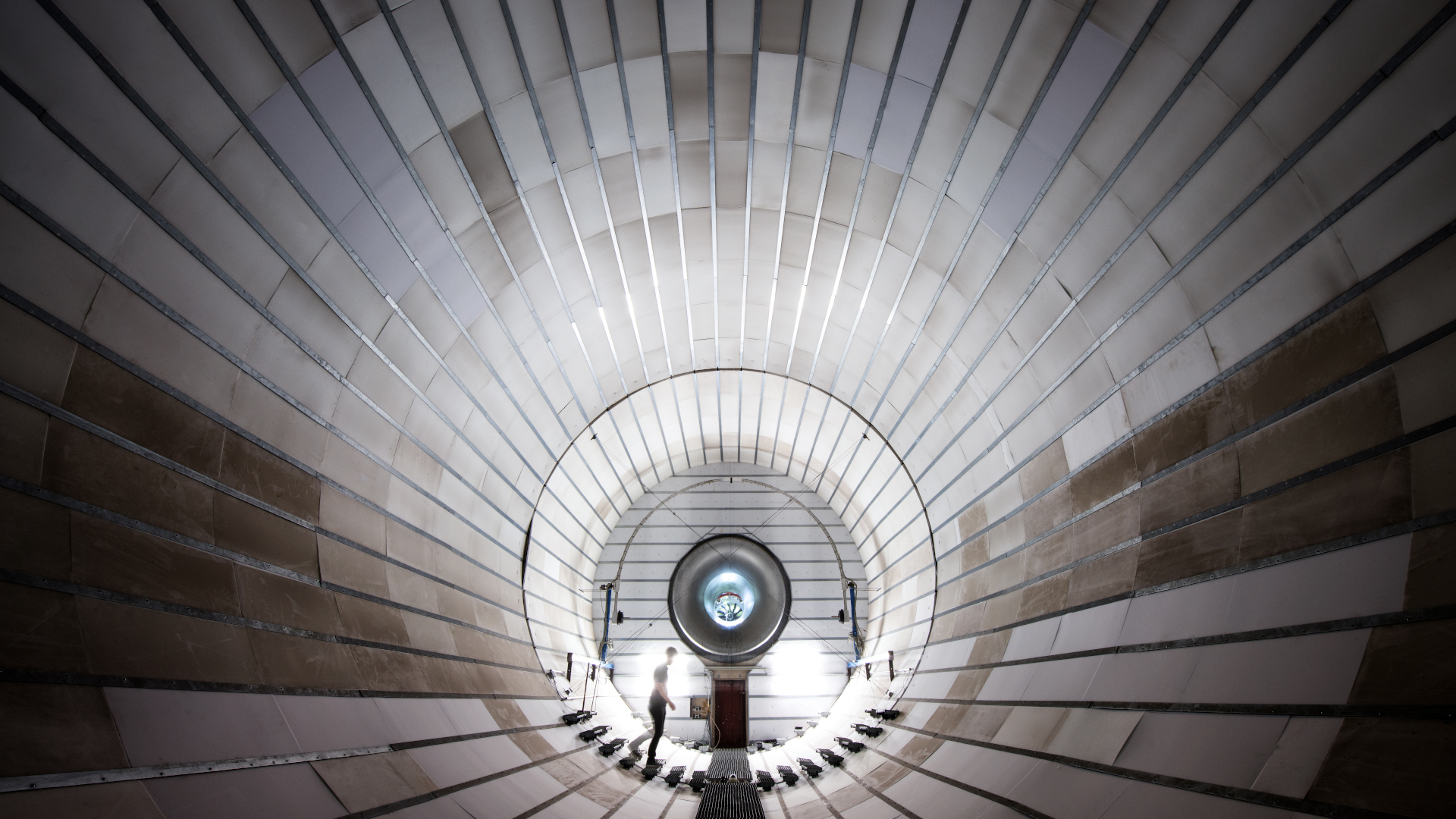
Settling chamber of the two-shaft multi-stage axial compressor test rig
The multi-stage two-shaft axial compressor test rig is available for the experimental investigation of axial machines. This test rig not only allows the investigation of a single- or multi-stage compressor, but also the operation of counter-rotating compressors and fans or low-pressure/high-pressure compressor combinations at different speeds.
For special investigations, such as acoustic tests and detailed measurements of the interactions of the shock-vortex system, the degree of turbulence must be improved with a suitable flow straightener. In addition to the speed control of the drive motors, the outlet throttle downstream of the test object is used to adjust the operating point. This is an electrically operated ring throttle. A pump protection/pump detection system is installed in this area. The system minimises the number of pump surges as the stability limit is approached.
The institute has several extensively instrumented test beds covering a wide range of aircraft engines and stationary gas turbines. These include Rig250: representative of transonic front stages, UHBR rig: scaled fan rotor of a high-bypass engine, CRISP rig: counter-rotating fan rig.

