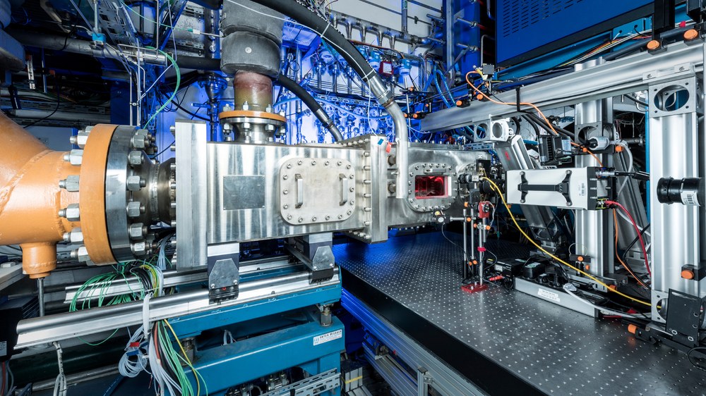
The large-scale high-pressure combustor test facility 1 (HBK1) system forms the supply and operating environment for various measuring sections. These are designed to be able to test full-size gas turbine burners under realistic operating conditions. Thus, the HBK1 is operated with single-burner combustion chambers as well as with multi-burner sectors. All combustion chambers not only have a geometrical similarity to the original operating environment, but also the distribution of cooling, mixed and secondary air analogous to the engine combustion chamber. In addition, the combustion chambers have full optical accessibility. This makes it possible to use optical measurement technology to record the processes and interactions in all zones and areas of the combustion chamber without influencing the reacting flow field.
Due to the possibility in the HBK1 to control all air and fuel mass flows, as well as the pressure independently of each other, a wide, comprehensive operating field including off-design points can be covered and controlled. New technical innovations to reduce pollution in aviation can be investigated very quickly in a TRL-4 environment in HBK1. This is made possible by the use of modular combustion chambers manufactured using the laser melting process (SLM).
Characteristics of the test bed
Technology Readiness Level 4
Static pressure up to 25 bar
Preheating temperature of compressed air up to 900 K
Air mass flow preheated up to 4.5 kg/s. Up to 10 kg/s of preheated and cooling air in total
Variable distribution of preheated air
The following are used: single-burner combustion chambers, multi-sector combustion chambers
Full optical accessibility in all combustion chamber zones
Liquid and gaseous fuels incl. hydrogen
Reasearch topics
Fuel treatment, atomization, evaporation, dispersion
Pilot/main burner interaction, flow field, stabilization, heat release
Pollutant formation / soot production
Mixing of secondary and mixed air
Burner-Burner Interactions
Investigation of combustion chamber exit parameters (=turbine inlet)
Burnout
Thermoacoustic stability
Use of SLM – manufactured combustion chamber components and combustion chambers
Mesaurement technology
Particle Image Velocimetry (PIV)
Laser Doppler Anemometry (LDA)
Phase Doppler Anemometry (PDA)
Kerosene LIF
Mie scattering
Laser-induced incandescence (LII)
Tecnical Data
Static pressure | 25 bar |
Preheating temperature of the compressed air | up to 900 K |
Air mass flow | up to 4,5 kg/s preheated up to10 kg/s cooling air total |
Liquid fuels | Kersoene, SAF |
Gaseous fuels | Hydrogen, methane |

