

Steep inter compressor ducts (ICDs) are a promising solution for reducing the environmental impact of future aircraft engines through lower fuel consumption. This fuel saving is due to several factors. These include the lower weight of the compact engine, the resulting possibility of a lighter support structure in the engine nacelle, the improved centre of gravity and the lower drag.
Investigations on the test bed can be carried out under conditions similar to those in turbomachinery in terms of Mach and Reynolds numbers. This includes the ability to extract air from the ICD via an exhaust system. This means that all the major operating points of an aircraft engine, such as take-off, flight and climb, can be covered by the test bed.
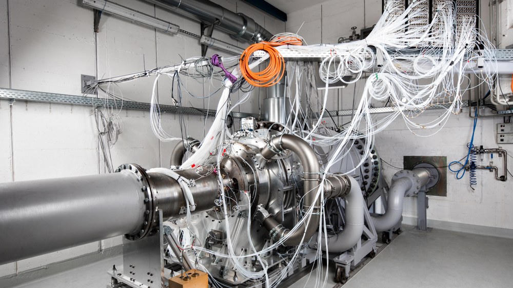
The test rig has the capability of variable swirl generation to realistically simulate the discharge conditions of the final low-pressure compressor rotor. This allows a realistic inflow to the ICD to be generated. A detailed flow image can be obtained using boundary layer ridges, traversable multi-hole probes, a large number of static pressure measurement holes, laser optical measurement methods and the ability to visualise the flow using oil painting images.
A detailed flow image can be obtained using boundary layer ridges, traversable multi-hole probes, a large number of static pressure measurement wells, laser-optical measurement methods and the possibility of flow visualisation using oil painting images.
Charactersitics of the Inter Compressor D
- Swirler as a rotor replacement: The test rig provides the ability to create variable swirl to realistically simulate the discharge conditions of the last low pressure compressor rotor. This allows a realistic inflow to the ICD to be generated without the need to install rotating components. This enables cost-effective test campaigns with low design effort.
- Comprehensive, advanced measurement technology: Boundary layer chambers, traversable 3- and 5-hole probes, a variety of pressure holes, laser-optic measurement methods and the ability to visualise flow using oil paintings provide a detailed picture of the flow.
- Wide operating range: All important operating points of an aircraft engine, such as take-off, flight and climb, can be investigated with the test stand. A wide range of independently adjustable Mach and Reynolds numbers allows these operating conditions to be closely approximated.
- Bleed air extraction: In real aircraft engine operation, air is always bled from the ICD to ensure safe engine operation in any operating condition. During a transition to another operating point, a lot of air is typically bled from the ICD. The bleed air system allows the operating points to be set even more realistically.
Research Topics
Technology Readiness Level 3-5
Detailed investigation of interstage compressor channels
Validation tests for new ICD concepts
Provision of detailed measurement data for CFD validation
Investigation of active and passive flow control, transition behaviour
Technical Data
Inlet | |
Mach number | 0.0 – 0.4 |
Reynolds number | 8x10⁵ – 5.3x10⁶ |
Mass flow | 0.1 kg/s – 30 kg/s |
Total pressure | 0.6 bar – 3 bar |
Total temperature max. | max. 310 K |
turbulence level | 0.6 – 4.0 % |
Specifications | |
Air extraction mass flow | 0 – 5 kg/s |