SIAM

The SIAM (low-noise medium-haul aircraft) project aims to design an aeroplane for the longer-term horizon of 2050 that would be significantly quieter than even those current conventional aircraft with the most effective noise reduction technologies. SIAM seeks to address the ambitious noise reduction targets of the EU's 'Flightpath 2050' strategic paper.
Unlike conventional practice, noise reduction considerations in the SIAM project are incorporated into the design of the aircraft configuration and flight procedures from the start, enabling noise sources to be reduced from the outset or possibly avoided entirely. The studies go beyond the preliminary design phase, progressing into a detailed aircraft design. Additionally, a high-fidelity (HiFi) simulation is being developed to provide initial proof of design success, along with a new procedure for experimentally verifying sound radiation from the entire aircraft in an acoustic wind tunnel. This testing is conducted using a reference aircraft (an A320, with and without noise reduction technology).
SIAM also provides the basis for a follow-up project to achieve the first experimental-numerical verification of noise and performance for an unconventional aircraft design.
Project content
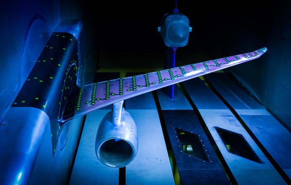
As part of the SIAM project, the DLR Institute of Aerodynamics and Flow Technology (Department of Technical Acoustics) aims to conduct aerodynamic and acoustic tests on a large-scale model of the ATRA (Advanced Technology Research Aircraft). With a half-span of 1800 millimetres, the model will be mounted on a support structure comprising the lower fuselage and a wing mast. This wind tunnel model incorporates innovative noise-reduction components and an unprecedented level of detail in its landing gear. Additionally, both the model and the support structure are equipped with numerous pressure measurement ports, with the tubing for these ports initially gathered within the fuselage through couplings. An electric nacelle attached to the model generates airflow to simulate engine noise. All necessary cabling must be routed through the wing mast to the wind tunnel floor, where control units and instruments are located. This design complicates construction due to the limited space available for instrumentation channels.


