Fibre composite structures for MASCOT

Just as a car has a chassis, spacecraft also have a basic structure. But the big difference is that the acceleration forces exerted on the structure of a spacecraft during a rocket launch are many times greater. As such, the structure of MASCOT has been designed to withstand a maximum local acceleration of almost 50G, which equates to ≈50 times the acceleration due to gravity on Earth. In addition, when designing spacecraft structures, more attention needs to be paid to lightweight construction. This determines the component rigidity – in other words, the component's resistance to deformation when subjected to loads, which should ideally be very high and has a bearing on the structure’s mass and geometry. The combination of these factors presented a particular challenge for MASCOT. The parameters meant that the lander could be barely bigger than a shoebox and that its maximum take-off mass could be no more than 10.9 kilograms, including all of its instruments, systems and interface structure, which ensures the connection between the lander and the Hayabusa2 probe. The MASCOT lander’s structure was developed and assembled at the DLR Institute of Composite Structures and Adaptive Systems.


The MASCOT lander structure – much more than a shoebox
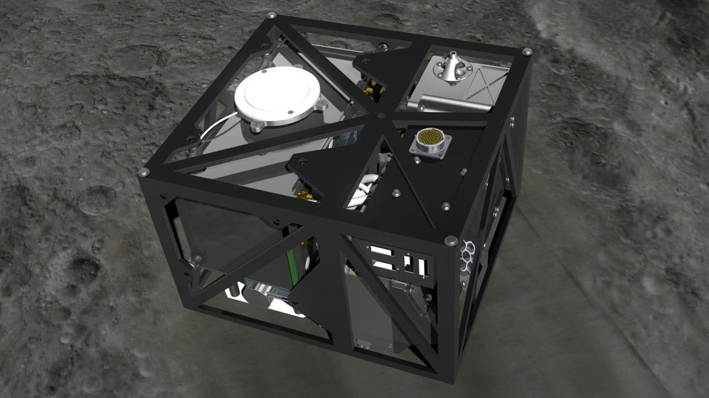
Measuring 28 centimetre x 29 centimetre x 21 centimetre, the MASCOT lander is comparable to the size of a shoebox. Its interior is divided into two sections. Approximately one third is the 'cold science compartment', which contains the payloads, while the other two thirds comprise the 'warm bus compartment', which contains a common dedicated electronics box, the battery (CNES MASCOT minisite) and the mobility mechanism. While the cold science compartment is unheated, the warm bus compartment is heated and insulated with 21 layers of foil (alternating between a layer of coated polyimide and a layer of separating mesh. Given the arrangement of the different components, the challenge with the structure, in addition to the very limited space, was that the components had to be securely fastened to one side, while on the other side, three of the four payloads had to have a clear field of vision for the execution of the experiments. In order to do this, and with the aim of achieving the most lightweight construction possible, a framework structure was designed, featuring trusses connected at bearing points. Ideally, the trusses were to absorb only tensile and compressive forces along their axes, which made fibre-reinforced plastic – with its orthotropic material properties – the first choice of suitable material. These orthotropic properties, whereby the particular material characteristics are much more pronounced in a particular direction, rather than one perpendicular to it, were deployed for the fibre-reinforced plastic by applying particular fibres parallel to each other. Opting for carbon or glass fibres, for instance, which, compared to plastic, are significantly stiffer and have a higher strength, and aligning these along the longitudinal axis of the plastic truss, allowed the scientists to make the most of their outstanding axial mechanical supporting properties.
For MASCOT, the fibres are reinforced with very stiff carbon fibres (M55J). In addition to the required strength, they have a high level of stiffness. This ensures that vibrations to the spacecraft caused by the rocket engines during the launch, for instance, are not intensified and passed on to the instruments. This is referred to as a mechanical decoupling of systems. In order to make MASCOT’s framework structure even lighter and protect the trusses against bending or buckling, a ‘sandwich design’ was used, as opposed to pure carbon fibre-reinforced plastic (CFRP). As such, very thin sheets (surface layers), in some places only 0.125 mm thick, were glued on both sides to a foam core that kept them evenly spaced. In MASCOT’s case, this is made of low-density foam, which further enhances the lightweight design.

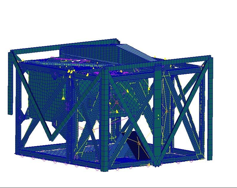
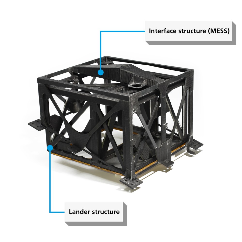
Figure 4 shows an example of the semi-finished individual parts required to create the surface layers for one of the side truss walls of the lander framework. The cut parts, which consist of a finished fibre-plastic mixture (known as prepreg), with the fibres only running in one direction, are first placed in a mould (see Fig. 5) and thus joined together to form a truss-shaped surface layer. A second surface layer is then made, before both are glued to the foam core, thus creating the truss side wall highlighted in Fig. 3. Another four outer framework walls and the central dividing framework wall are produced in the same way. Finally, in order to create a three-dimensional structure out of the individual framework walls, these must be connected to one another along their outer edges using what are known as shear straps. These L-shaped angle profiles (see Fig. 3, left) are also made of CFRP, but the fibres are arranged in two directions, perpendicular to one another, and woven together like a canvas fabric. Moreover, the shear straps are aligned at a 45-degree angle to the axis of the trusses, allowing loads to be transferred from one framework wall to the next. The top side of the lander also consists of two sandwich components, but these cover the entire surface, while both the face sheets and the honeycomb core are made of aluminium. Both of these sandwich components are bolted to the rest of the MASCOT’s CFRP fibre composite structure, leaving an opening for the installation of the instruments and system components within the lander. The two upper sandwich components are made of aluminium because these are ‘radiator surfaces’. Such surfaces create a heat sink, so that excess heat energy (for example from the on-board computer) can flow there, from where it is distributed across the highly thermally conductive aluminium surface layers, and from there is released into the air by thermal radiation. In addition to functioning as a radiator, the larger of the two aluminium sandwich components also has a structural function, without which the overall structure would have a much lower stiffness.


In total, the lander consists of around 250 parts, which were cut out by machines and glued together and assembled by hand for over 2.5 months. In total, the structure of the lander weighs around 800 grams. This consists of ≈550 grams for the fibre composite components and ≈260 grams for the two aluminium radiators. This makes the structural mass less than nine percent of the overall mass.
MASCOT’s interface structure – the hidden hero
When the MASCOT lander is released from its mother ship and lands on the asteroid, all of the attention will move to a hidden yet vital structural component. Embedded in a section of the Y-side surface of the Hayabusa2 probe (Figs. 6 and 7) is the Mechanical and Electrical Support Structure (MESS) between the MASCOT lander and Hayabusa2 (Fig. 8). This forms the mechanical and electrical interface between the two spacecraft and, like the lander, is designed as a framework structure.

The tilted mounting position of the MASCOT lander in the side wall of Hayabusa2 presents a particular difficulty for the structural design of this component and the necessary stiffness of the entire system. As such, Hayabusa2 has two solar panels that are folded during the rocket launch. One of these panels is located directly in front of the side wall that contains MASCOT, among other units, so the lander is positioned in a section of the side wall, with most of its body protruding into the interior of Hayabusa2. When the panels are deployed, they are just above the cutout that contains MASCOT. In order to prevent the MASCOT lander from bumping against the panel during the separation process, it is mounted at an angle of 15 degrees to the side wall. To keep the mass to a minimum while also ensuring the required stiffness of the overall system, the framework struts of the interface structure are made of solid CFRP, unlike those of the lander. Each of these consists of 24 individual prepreg layers for each strut, with 85 percent of the fibres aligned along the longitudinal axis of the strut. In the upper section of the framework structure, a sandwich truss like a hollow box girder is positioned along the plane of symmetry of the interface structure, thus accommodating the detachable central connecting bolt between the lander and the interface structure (cf. Figure 8). From there, the CFRP framework struts also connect to the counterbearing points of the MASCOT lander at the four top corners of the interface structure and to Hayabusa2. The lander is pulled over the central bolt with a total of 2000 Newtons (equating to approximately the weight of four bags of cement on Earth) into the outer bearing of the interface structure. Made of hardened stainless steel, the counterbearings have a cone-shaped receptacle, so that they can accommodate longitudinal forces, while still allowing rotation. Despite the high longitudinal and lateral accelerations during the rocket launch, these hold the lander securely in place but avoids wedging.

Structural specifications | ||
|---|---|---|
Structural design | Quasistatic load Random load First natural frequency | 50G 9.8 OGRMS 125 Hz |
Dimensions | Lander Interface structure | 280 mm × 290 mm × 210 mm 370 mm x 340 mm x 230 mm |
Mass | Entire system Lander structure Interface structure (MESS) Elektronics box (empty) | 10.9 kg 0.81 kg 0.68 kg 0.73 kg |
In order to prove that the structures meet the mechanical and systemic requirements, they were put through their paces and approved for use by the DLR Institute of Space Systems. Among other things, the 'structure models' were used to perform tests on a vibration platform, which mimicked the acceleration loads of the rocket launch. These were the most demanding and crucial mechanical tests for the structure. Once the testing was successfully completed, it was possible to start the construction of the spacecraft’s flight unit. It also underwent the shock load test, which exerts very high pulse-modulated acceleration forces on the structure and simulates the separation of the rocket stages. Another and truly spectacular test was a simulation of the ejection of MASCOT from the interface structure, replicating the process that will occur at the start of the landing phase on Ryugu, the target asteroid. In order to mirror the separation process as accurately as possible – which meant performing the tests without the disruptive influence of Earth’s gravitational pull or air friction – they were carried out in parabolic flights and in the drop tower in Bremen. The MASCOT lander, connected to its interface structure, was installed in a capsule and dropped from a height of 110 metres within an evacuated tower. For the brief moment of falling, the experimental setup is ‘microgravity‘, so that a separation of the two systems within the capsule and during the fall provides a highly realistic simulation of MASCOT’s ejection at the asteroid.
In addition to the primary structures (MASCOT lander structure and interface structure), there is an array of what are known as secondary structures, which are built into both primary structures as additional components. These include the electronics box (Figure 9), the antenna ground plane (Figure 10) and the so-called push-off plate as part of the MASCOT separation mechanism (Figure 11).


