
Application of Particle Image Velocimetry: Transonic flows

Over the past two decades the non-intrusive Particle Image Velocimetry (PIV) has matured from its developmental stage to a reliable whole field measurement technique for industrial aerodynamics. Nowadays the PIV technique is capable to capture all three velocity components in a plane of a flow instantaneously and it increases its spatial and temporal resolution continuously by applying novel developments in optics, sensor- and laser techniques and by implementing improved evaluation- and post-processing algorithms.
A mobile PIV system fulfilling the requirements for successful applications in trans- and supersonic flows and measuring the velocity fields accurately has been developed in the past decade. In order to cope with seeding problems, vibrations, optical access, synchronisation triggering, high mass flow rates, the pressure gradients and temperature range in such facilities several technical extras for controlling the measurement have been adapted in the PIV system. Especially the homogeneous seeding of the flow with suitable tracer particles and sufficient density is one of the major problems in high-speed air-flows. In order to minimize the velocity lag in regions with strong positive or negative accelerations of the flow e.g. across shocks, in turbulent shear layers or in vortical flows very small tracer particles with a diameter of 1 µm or smaller are required.
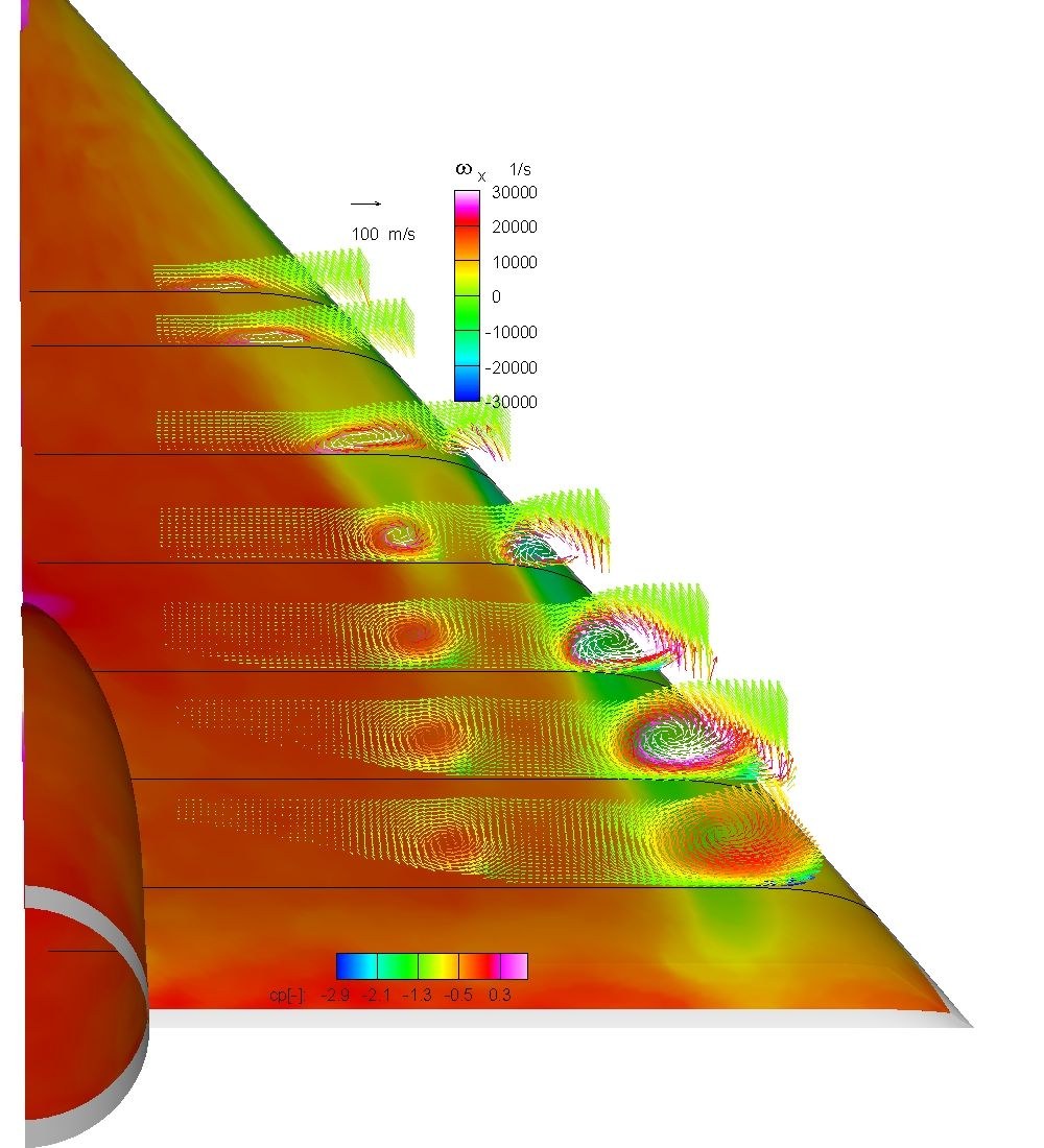
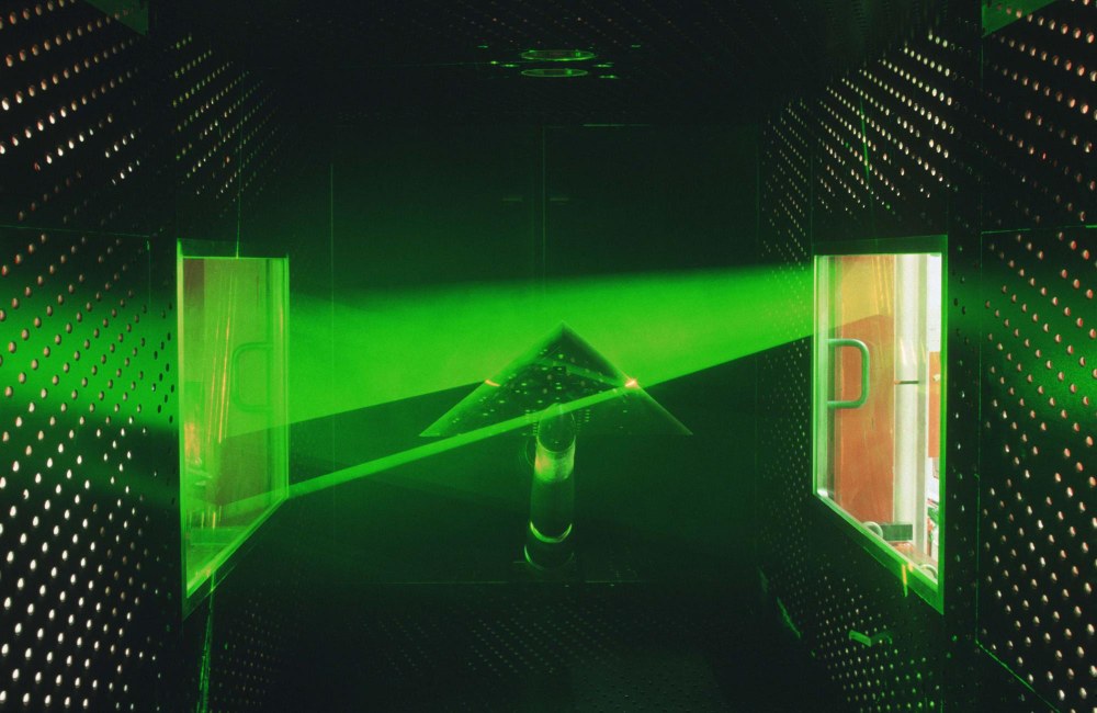
In the framework of the Vortex Flow Experiment 2 (VFE-2) project a subsequent application of PSP (Pressure Sensitive Paint), CFD and Stereo PIV on a generic delta wing with rounded leading edge in transonic flows provided a valuable data-set for validation of numerical codes and the understanding of the complex flow phenomena and topologies over the wing at different angles of incidence. After a PSP measurement in the transonic wind tunnel TWG of DNW in Göttingen has been performed the resulting pressure distribution over the surface of the delta wing was used as boundary condition for numerical simulations with the FLOWer code. This numerical result shows for a certain test case two parallel co-rotating vortices with different strength and origins. The Stereo PIV measurement has been performed immediately after the release of the numerical results in the TWG at various chord length, angles of incidence, Mach and Reynolds numbers (see Figure 1). For the certain parameter case, the "curious" double vortex has been found “again” and characterized with more details. The quantitative characterisation of the unsteady quality of these vortices, especially during the break-up process is not available otherwise. An example result of these Stereo PIV and PSP campaigns is shown in Figure 2. The local minima of the surface pressure distributions are oriented along and parallel to the vortex cores over the delta wing. The start of the secondary vortex structure with counter rotation between leading edge and main vortex is also visible.
In the framework of the DLR own projects HighPerFlex and AerostabilPIV measurements of the shock-wave boundary layer interaction above a wing, which was externally forced to flutter oscillations, were performed in the transonic wind tunnel TWG at Mach numbers between 0.5 and 0.8. Small amplitude oscillations of the wings are the general case in free flight of aircrafts under turbulent flow conditions. The aerodynamic properties of airfoils change sensitively under flutter conditions. One focus of interest on structure-flow interaction investigations in the field of aeroelasticity of aircraft wings is the flow separation due to shock wave induction and the flow around trailing edges, where local separation appears frequently. The chord position of a shock above a wing with flow separation wiggles under transonic flow conditions even at constant angles of incidence. An animation of several PIV measurements at different phase angles of the oscillation process can be seen at Animation 1. Under flutter conditions the shock position can oscillate with much higher amplitude (see PIV Animation 2), because at a certain angle of attack shock-wave boundary layer interactions become relevant up to periodically induced flow separation. The induced flow separation gets periodically locked-in to a certain flutter mode of the wing which leads to very strong aeroelastic forces.