Department Aeroelastic Experiments
The department Aeroelastic Experiments is committed to the planning, realization and analysis of challenging experiments in wind tunnels.
There is a significant risk of flutter in aircraft wings, wind turbines and aircraft engine blades. Flutter is an aeroelastic instability which, under simplified linear conditions, once set in motion will not stop. An oscillation of the wing or engine blade generates such a pressure fluctuation around the profile that it acts back on the wing or blade in such a way that it amplifies the initial oscillation and thus further amplifies the pressure reaction. If the parameters remain constant, the vibration and pressure reaction will grow together until a structural failure occurs. Therefore, a possible tendency to flutter must be considered, identified and prevented at the design stage. Aerodynamic damping can be used as a criterion for this.
Many methods are used during development to ensure flutter safety. Finite Element Methods (FEM) are used to determine the modes (eigenmodes) and frequencies (eigenfrequencies) at which the structure vibrates. These predictions are then validated by testing the first components or even entire prototypes. The aim is to ensure that the predicted vibrations match those of the real structure. After all, these are the vibrations that would occur in the event of flutter. On the aerodynamic side, CFD (Computational Fluid Dynamics) simulations are then carried out using these frequencies and vibration modes, from which the above-mentioned pressure changes are determined to simulate whether the vibration will increase or not. If the vibration and the resulting pressure changes (which act as forces on the wing or blades) are known, the aerodynamic work and damping done on the blades can be determined. If the damping is positive, the vibration will decrease, like a car that has driven over a pothole. On the other hand, if the aerodynamic damping is negative enough to overcome the structural damping, flutter will occur.

However, the pressure distribution and mode shape - and therefore the work and aerodynamic damping - are variables distributed over the blade surface with areas of high positive, i.e. highly damping, values and other areas of high negative, i.e. highly destabilizing, values. The total work or damping is then calculated as an integral over the entire surface, with a large proportion of the positive and negative values cancelling each other out, leaving only a small value that is positive or negative. Accurate simulations are essential to reliably determine these values!
Although we are able to accurately simulate aerodynamic damping using advanced CFD models, these simulations need to be validated against real experimental data. This is especially true for complex scenarios, such as transonic compression shocks, where the strength and location of the shocks change as the blade vibrates. Experiments are essential to assess such phenomena.
This involves simulating a combined vibration and flow situation in a test facility - in a wind tunnel or on a test rig - measuring many parameters, such as the blade vibrations and the fluctuating pressures that occur, and comparing the measured results with the computer simulations.
Modelling the test situation for turbomachinery blading is very challenging. There are many blades on a rotor or a stator which, in the case of the rotor, rotate and therefore generate a significant proportion of their flow through their circumferential speed or, in the case of the stator, may already be subjected to a circumferential component in the flow.
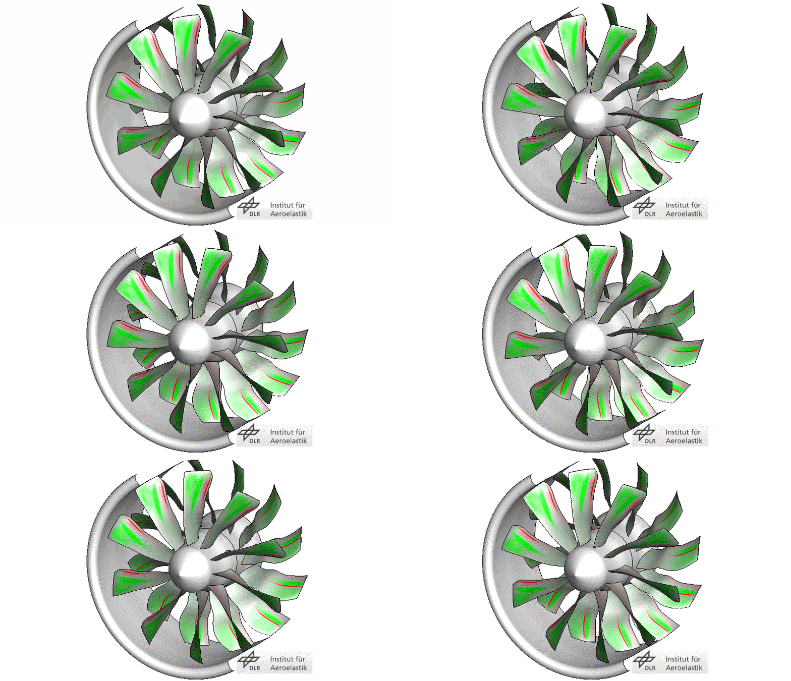
An engine blade does not vibrate on its own; the vibrations of the blades are coupled to each other. In addition to a coupling via their clamping points and the supporting disc, there is also a coupling via the aerodynamics. This coupling leads to a collective vibration pattern in which all blades vibrate synchronously with each other like a circulating wave, similar to a La-Ola wave in a stadium. This results in a phase shift between the neighboring blades performing the vibration, called the interblade phase angle (IBPA). This phase angle is an important parameter for analyzing the aeroelasticity of engine blades.
Experimental investigations on engine blades can be carried out in different wind tunnels and test rigs. In principle, a distinction can be made between how the rotating blades in the engine are simulated in the test rig: as a linear cascade, as an annular cascade or as a rotating compressor and turbine test rig (DLR Institute of Propulsion Technology). In a previous technical article on the non-rotating annular cascade test facility , we discussed the advantages and disadvantages of the different variants. Non-rotating annular cascades are best suited for aeroelastic investigations where the vibration induced pressure distributions on the blade surfaces are of interest.
In order to simulate these non-rotating annular cascades, we use our “Ringgitterprüfstand Göttingen”, RPG (Non-rotating annular test facility). Twenty blades (2D blade sections) are arranged in a closing annular cascade as in an engine. The special inflow conditions in the test rig are provided by inlet guide vane systems. Although the blades are stationary, i.e. they do not rotate, a flow is created through these inlet guide vanes as if they were rotating in the engine.
For the aeroelastic evaluation, the pressure distributions generated by the blade vibration are of interest. In order to do this, the blades have to be positioned exactly in this vibration pattern. Secondly, the pressure distributions must be measured where the pressure forces act: on the surfaces of the blades. In the annular cascade, all the blades can be set in a prescribed motion. And because the annular cascade does not rotate, it is easy to install a large number of sensors in the blades to measure the aerodynamic forces acting on them.
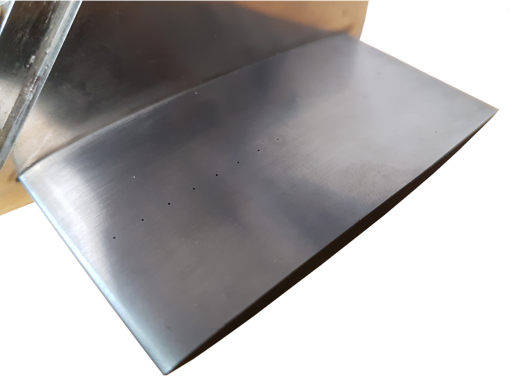
However, measuring the pressure distribution is no easy task - the pressure distribution on the blades is spread over the entire surface - every square millimeter counts. We currently measure the transient pressure distribution using piezoresistive pressure sensors, also known as 'Kulites'. These sensors are small and highly accurate, but they are expensive and require sophisticated data acquisition systems. Despite their small size, we still cannot measure the entire pressure distribution on the surface. This means that we do not know exactly what is happening between each measurement point. While it is possible to make assumptions about the evolution between measurement positions, especially when this is obvious, peaks caused by shocks, for example, or the evolution from the last measurement position to the leading or trailing edge cannot be easily interpolated.
For the next tests, we have therefore decided not to calculate work or aerodynamic damping directly from the measured pressure, but to compare the pressure distribution at the measurement points with our simulations. By comparing these pressure measurements, we aim to improve the accuracy of our numerical models and then use these validated models to calculate the aerodynamic damping more accurately.

In our next reports here, we will explain in more detail how we measure the pressures and blade movements, which parameters are relevant for the analysis and how they relate to each other, in order to gain a better understanding of the aerodynamic damping of engine blades.
Joachim Belz, DLR Institute of Aeroelasticity, Department: Aeroelastic Experiments
