Application of Pressure Sensitive Paint: Low speed flows

The challenge for low speed applications of PSP is mainly the improved accuracy, which is required due to smaller pressure differences in comparison to transonic flows. To achieve higher accuracy there are many items to cope with. Firstly DLR uses CCD camera systems with higher dynamic range (16 bit) and acquiring several images per data point to improve the signal to noise ratio by averaging these images. But increasing the dynamic range is not sufficient, because with higher accuracy other effects begin to play a more important role, like reflections, temperature differences, inhomogeneous illumination, etc. Many efforts are made to avoid reflections inside the wind tunnel and between windows. Special Xenon flash lamps provide a high power homogeneous UV illumination and simultaneously acquired infrared images provide information about the temperature distribution on the PSP coated surface.
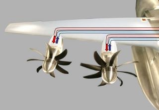
In the following as an example in Fig. 1 a half model in high lift configuration in the low speed wind tunnel of Airbus in Bremen is shown, which is equipped with propeller simulators. The special challenge here is mainly the strong temperature difference on the wing. This is due to the pre-heated pressurized air to drive the propeller simulators and the expanded (much colder) air, which both are guided through tubes inside the wing. Here the same paint as used in transonic applications, DLR02, is used. It shows a temperature dependence of about 0.3 %/K, which would lead to pressure errors of up to 4500 Pa at the observed temperature differences of up to 15 K (see Fig. 2). A correction of the temperature effect on the pressure reading is thus essential.
The temperature dependent calibration curves have been determined at the DLR laboratories using a calibration chamber capable of changing pressure and temperature of a paint sample independently. The triple of intensity, pressure and temperature defines the characteristics of the paint and enables us to calculate from two values the third one. Thus the temperature values from the infrared image and the intensity values from the PSP images at the same surface location must be used to finally determine the pressure distribution as shown on the right side of Fig. 2. The standard deviation between PSP results and several pressure tap values was found to be about 150 - 200 Pa.
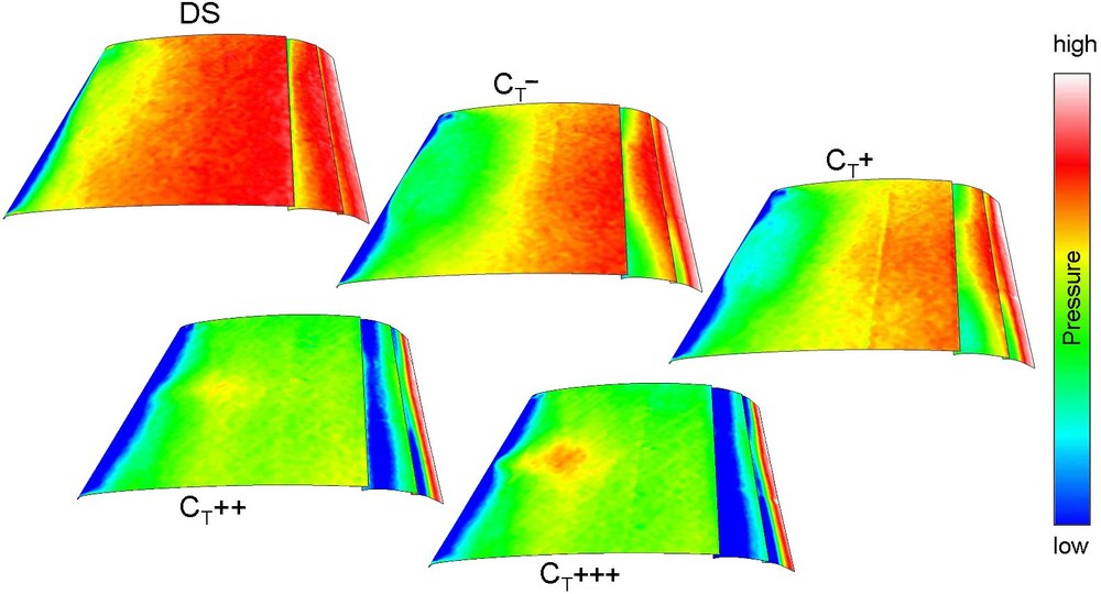
Fig. 3 shows the pressure distribution for a configuration without propeller blades (DS) and for increasing thrust levels at one angle of attack. It is clearly visible, that the propellers even running without thrust (CT-, CT+) improve the separation behaviour of the flow. Increasing the thrust further more (CT++, CT+++) leads to a reduced pressure on the main wing as well as on the flaps and subsequently to higher lift.
Currently the determination of loads by integration of PSP data especially for flaps in high lift configuration at low speed conditions is under research.


