Modal tests in the H135 production line to improve vibration prediction
April 29, 2024
Modal tests in the H135 production line to improve vibration prediction
Figure 1: View of the final assembly line for the H135 and H145 at Airbus Helicopters in Donauwörth
Credit:
Airbus Helicopters
Helicopters are aircraft with the ability to take off and land vertically. Due to these capabilities, helicopters are often used for fast and local air transport, as required, for example, for rescue operations. The ability to take off and land vertically is achieved by the lift of rotating wings (i.e. rotor blades). The rotor with the aerodynamically shaped rotor blades rotates at a constant speed. The ability to change the lift is made possible by a complex mechanism for adjusting the angle of attack of the rotor blades.
Why structural dynamics is relevant for helicopters
In hover flight, it is sufficient if all rotor blades have a constant angle of attack. During fast-forward flight, the rotational speed of the rotor blades is superimposed on the airspeed. The blade turning forward (i.e. in the direction of flight) will have a higher onflow velocity than the blade turning backward (i.e. against the direction of flight). With the same angle of attack, the blade turning forward would generate a greater lift force than the blade turning backward. Equalising the lift forces of both blades is achieved by actively changing the angle of attack during each revolution of the rotor. In this way, the angle of attack of the blade turning forward can be reduced, while the angle of attack of the blade turning backward is increased. This active angle of attack control during the rotation of the rotor blades is achieved with the aid of the swash plate and control rods.
Actively changing the angle of attack of the rotor blades during rotation requires time-periodic, oscillating control forces. These forces are generated by hydraulic actuators in the fixed system, which adjust the position of the swash plate and thus transfer the forces via the control rods to the rotating system. The oscillating forces generated in flight are also transmitted in reverse from the rotor via the control rods to the swash plate and then via the actuators to the main gear box of the helicopter. The main gearbox is installed on the roof of the helicopter. It transmits the drive power of the engines to the main rotor and the tail rotor. The main gearbox is connected to the fuselage of the helicopter. The oscillating forces are transferred from the rotor to the airframe via this connection.
Helicopters are lightweight structures. As such, they tend to vibrate. Since helicopters are susceptible to vibrations on the one hand and are dynamically excited due to the oscillating forces from the rotor control on the other hand. Therefore, the topic of vibrations is of particular importance in helicopter design. If vibrations occur, they can make the helicopter difficult to operate and can interfere with missions such as patient transport or aerial reconnaissance with high-resolution cameras. In order to reduce vibrations, a variety of measures such as rotor isolation systems are used in the helicopters currently in production. In addition, Airbus Helicopters, a DLR cooperation partner, has already achieved a significant reduction in vibrations with a newly developed five-blade rotor system with a frequency range optimal for the H145 helicopter type.
Simulations to become even more meaningful
To design a low-vibration helicopter, the oscillating forces from the rotor control system must be calculated in a first step. With the use of modern aero-mechanical analysis methods such as CFD [1] and MBS [2], significant progress has been made in this area. In a second step, the forces from the rotor control system, calculated using the modern analysis methods, must then be introduced into an FE model [3] of the helicopter airframe as vibration-exciting forces. These models can then be used to check to which extent vibrations are propagating in the helicopter airframe. Based on corresponding simulations, suitable measures can be developed for the targeted reduction of vibrations. However, it was found that the prediction accuracy of current FE models should be improved.
FE models for helicopters are created during the design phase with the help of CAD models and material properties and are used afterwards for structural dynamic analyses. At the end of the design phase, a prototype of the optimized design is built. Its structural dynamic behaviour is determined experimentally by means of a so-called Shake Test or Ground Vibration Test. The results of the Shake Test can be compared with simulation results generated using the FE models. If the deviations between test and simulation are too large, the simulation models must be adapted to reality. However, a complete helicopter is a very complex system and the possible sources of error in the analysis models can be numerous. Therefore, this goal is difficult to achieve.
Within the scope of the LuFo [4] project “eVolve” DLR and Airbus Helicopters are pursuing a new approach. The structural dynamic behaviour of individual assemblies of a helicopter is determined in smaller component tests. The FE models of the individual assemblies can be checked and improved separately. The improved models of individual components are then combined to form larger assemblies. These assemblies can then be examined again in a test with regard to their structural dynamic behaviour. The simulation models of the assemblies can then also be adapted to the test data. In this way, a highly accurate simulation model for the complete helicopter is built up in several steps from improved models of its components and assemblies. This improved simulation model is then particularly suitable for the development of even lower-vibration helicopters. In order to realize this research project, a helicopter was selected in advance and accompanied on the production line in Donauwörth. The experiments therefore did not take place in laboratories, but at various assembly stations on the production line.
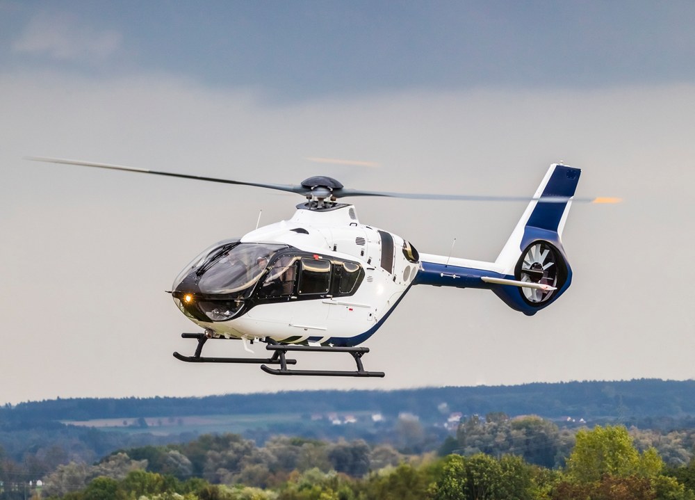
The helicopter tested within the scope of the eVolve project should be most representative in its dynamics characteristics. In addition to the existing (complex) basic structure, a helicopter can be significantly modified according to customer requirements. This means that helicopters are unique items that are equipped with features such as a cable winch, radar, camera, stretcher, etc. In the test planning, a specimen was therefore selected for the experiments that had as few unusual items of equipment as possible. Such a helicopter is shown in Figure 2.
Figure 2: Airbus Helicopters H135 in flight
Credit:
Airbus Helicopters
The vibration behaviour of a helicopter changes as the construction stage progresses. There are assembly stations at which the mass or stiffness of the overall structure changes particularly strongly. These are therefore particularly relevant in terms of structural dynamics three of these are shown in Figures 3-5.
Figure 3: H135 assembly station A
Experimental setup (left) || Comparison of a numerically (coloured, deformed areas) and experimentally (red arrows) determined mode shape.
Image: 1/3, Credit:
Airbus Helicopters & DLR (CC BY-NC-ND 3.0)
Figure 4: H135 assembly station B
Experimental setup (left) || Comparison of a numerically (coloured, deformed areas) and experimentally (red arrows) determined mode shape.
Image: 2/3, Credit:
Airbus Helicopters & DLR (CC BY-NC-ND 3.0)
Figure 5: H135 assembly station C
Experimental setup (left) || Comparison of a numerically (coloured, deformed areas) and experimentally (red arrows) determined mode shape.
Image: 3/3, Credit:
Airbus Helicopters & DLR (CC BY-NC-ND 3.0)
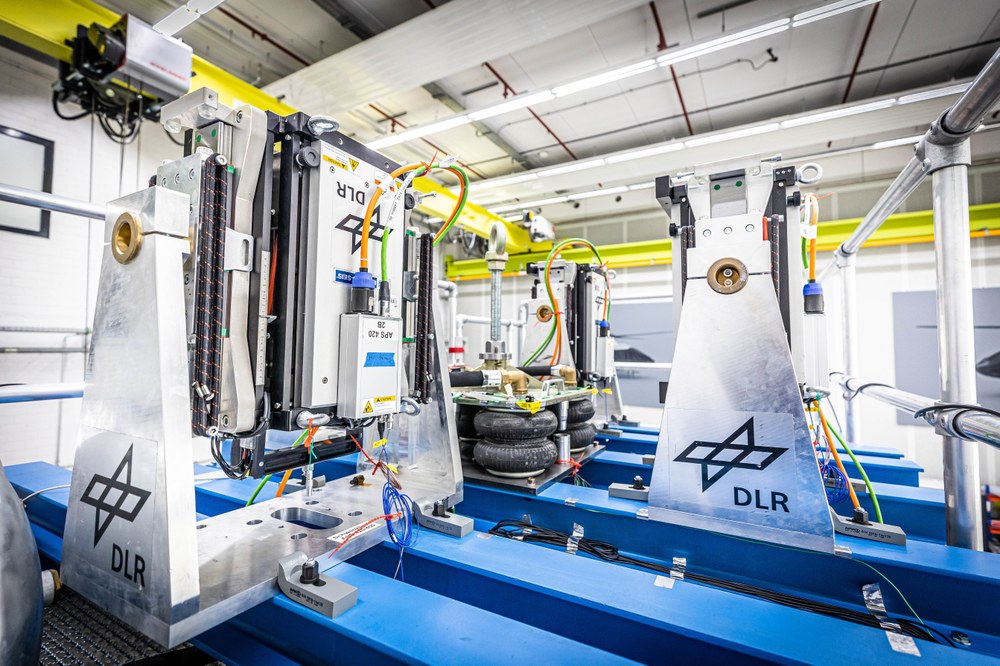
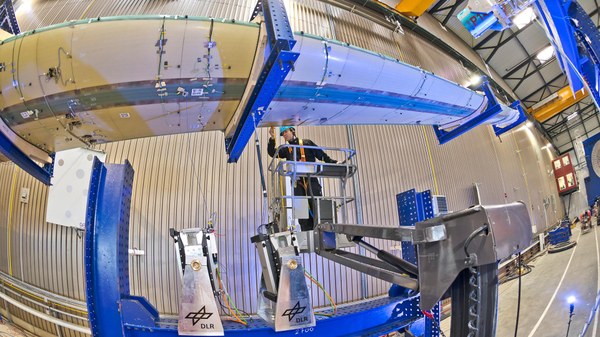
The experiments at these selected stations were carried out using mobile measuring equipment during ongoing production operations (see Figure 6). During the experiments, the helicopter was softly suspended on bungee cords in the respective construction state. These bungee cords ensure a defined boundary condition, which facilitates comparison with simulations. At the first assembly stations, the helicopter still consists of very few components. It is therefore possible to excite vibrations of the structure using an impulse hammer. In later construction stages, the use of electrodynamic shakers is required for the excitation of the helicopter. The response is measured at many different points using piezoelectric sensors. Digital signal processing and system identification methods are used to create a representative dynamic equivalent model from the test data. The sensor positions had to be accessible at the various assembly stations, which had to be considered in the test planning. In order to minimize disruption to the production process, the vibration test equipment must be completely removed from the helicopter between the modal tests at the various assembly stations.
Figure 6: DLR measuring equipment
With such shakers, the helicopter suspended in the test frame is excited at the rotor head.
Credit:
Airbus Helicopters
Figure 7: Monitoring and evaluation of the Shake Test at Airbus Helicopters in Donauwörth
Credit:
Airbus Helicopters
DLR is a leading provider of complex structural dynamics experiments. Nevertheless, these tests on the helicopter in the production line are characterized by special requirements and circumstances. In particular, it must be ensured that production operations are not interrupted by the experiments. For meaningful results, it is necessary that all essential components are available or assembled at the respective station at the time of the test. This requires functioning supply chains, which were still interrupted by the effects of global crises and the COVID-19 pandemic during eVolve. The success of the measurement campaign therefore required a high degree of flexibility from all partners involved.
Results and next steps
Selected results of this extensive measurement campaign, in which measurements were taken at 10 different stations with an average of 125 sensors, are shown in Figures 8-17.
Figure 8: H135 component test station 1
Image: 1/10, Credit:
Airbus Helicopters & DLR (CC BY-NC-ND 3.0)
Figure 9: H135 component test station 2
Image: 2/10, Credit:
Airbus Helicopters & DLR (CC BY-NC-ND 3.0)
Figure 17: Fully assembled helicopter, as tested in the Shake Test
Image: 10/10, Credit:
Airbus Helicopters & DLR (CC BY-NC-ND 3.0)
These are modes of vibration of the helicopter at the corresponding stations. Each arrow represents the characteristic contribution of a sensor to the mode of vibration. The deformed coloured areas show the corresponding simulation results generated by Airbus Helicopters for the helicopter at the respective assembly station.
The comparison of the simulated and experimental results is the basis for adapting the simulation models. This adjustment is carried out so that the simulation models reflect reality as closely as possible. The recorded vibration data (mode shape, natural frequency, damping, etc.) are essential parameters for this. However, easy to determine and relevant parameters to structural dynamics, such as the mass of the assembly or component, are also properties to be taken into account. These were therefore determined at the respective assembly stations and compared with the simulation models. The synthesis of the validated (partial) models results in a more meaningful simulation model for the dynamic analysis of the overall helicopter.
This procedure, in which structural dynamic tests were carried out on successively assembled subcomponents, was jointly developed by DLR and Airbus Helicopters as part of eVolve and demonstrated on a current helicopter model. This not only allows the models of the corresponding assemblies to be checked and improved at an early stage, but also enables important modes of vibration to be identified for these assemblies. In this way, the low-vibration helicopter is designed using more accurate simulation models. Expensive design changes in late design phases can thus be avoided. Airbus Helicopters plans to use this approach in future helicopter developments.
Glossary
[1] CFD: Computational Fluid Dynamics, i.e. numerical methods for flow calculation.
[2] MKS: Multi Body Simulation, numerical calculation method for analysing intricate movements and the resulting forces in components.
[3] FE: Finite element (method), a procedure that is often used to answer mechanical questions for structures with complex geometry. The structures are subdivided into smaller areas, so-called "finite elements", for which the corresponding equations can be set up more easily.
[4] LUFO: Aviation research programme of the Federal Ministry of Economics and Climate Protection (German: Luftfahrtforschungsprogramm; VI programme call)
Authors:
Marc Böswald and Johannes Knebusch, Department of Structural Dynamics and System Identification, DLR Institute of Aeroelasticity


