Aircraft should be as light as possible. To achieve this, their primary structure (airframe) is optimized for given operating loads. Precise knowledge of the loads occurring during operation is of particular importance for the sizing of the primary structure.
Load assumptions in aircraft design
The effects of static loads (e.g. lift and maneuvers) and dynamic loads (e.g. gust encounter and/or turbulence) are analyzed in aircraft design using models and assumptions. The validation of these models can help to avoid overly conservative load assumptions and thus to design an optimized structure that is adapted to the load.
The loads to be considered comprise a large number of load cases that can occur during the life of an aircraft. The experimental determination of actual loads from a variety of flight conditions and maneuvers can help to improve the load assumptions for the aircraft design and also to better estimate the fatigue life of the airframe.
Internal loads and strain measurement points
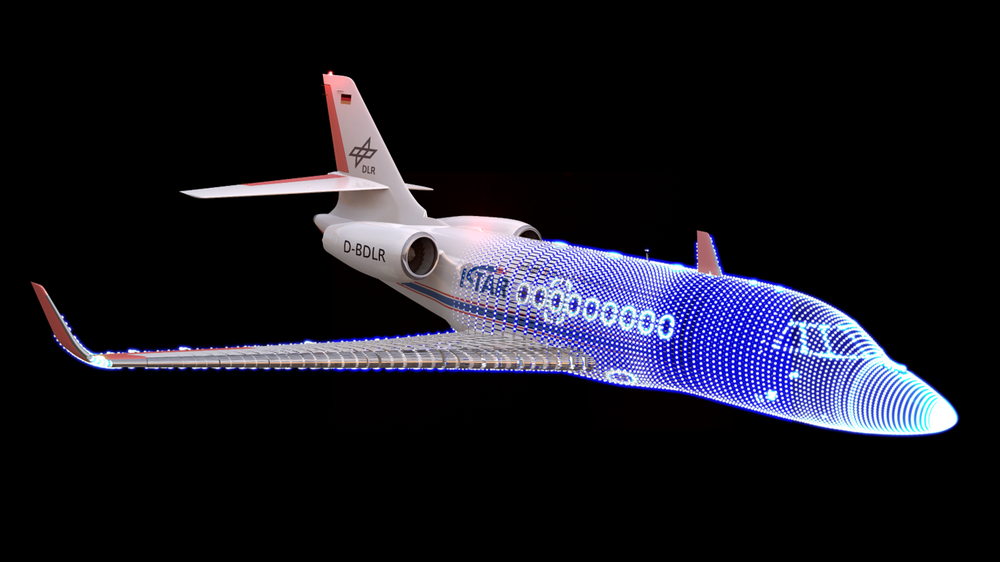
External loads are in equilibrium with internal loads (i.e. cut loads or stress resultants). Cut loads, which are of particular interest for sizing, include, for example, bending moments, shear forces and torsional moments in wings or empennage. Sizing means determining the minimum size of structural components so that operating loads can be borne safely. For this purpose, the DLR research aircraft ISTAR (In-Flight Systems and Technology Airborne Research) - a Dassault Falcon 2000 LX - was equipped with a permanent instrumentation of strain gauges. This makes it possible to experimentally determine the cut loads in the wings and empennage during flight.
The strains due to the external loads are recorded with strain gauges at 40 measuring points on the ISTAR. At each measuring point, 4 strain gauges are interconnected in a full bridge. This increases the sensitivity of the instrumentation while at the same time reducing the influence of undesirable strains (e.g. due to thermal influences).
Calibration and Skopinski method
Direct determination of the cut loads from measured strains is only possible for structural components with simple geometries and known material properties. For complex structural components or even assemblies consisting of different materials, the instrumentation must be calibrated for the experimental determination of loads.
For this purpose, known static loads with specified positions and directions are applied to the structure and the associated strains are recorded at all measuring points. If the number of load cases is greater than or at least equal to the number of measuring points, a linear relationship between loads and strains can be derived.
For the experimental determination of the loads - where the external load is not known beforehand - the strains are measured first. Based on the derived relationship between the loads and strains, the loads that are actually applied can now be determined. This technique (Skopinski method) was developed by NASA in the 1950s and is still used today.
ISTAR and strain gauge instrumentation
The instrumentation of ISTAR for aeroelastic investigations was developed in co-operation between the DLR Institute of Aeroelasticity and Dassault Aviation. The positions and types of strain gauges are shown in Figure 1. So far, only strains of the primary structure could be recorded during flight experiments. There was no calibration for determining the associated loads. This requires a special test environment, which was provided by Dassault Aviation at their flight test center in Istres near Marseille.
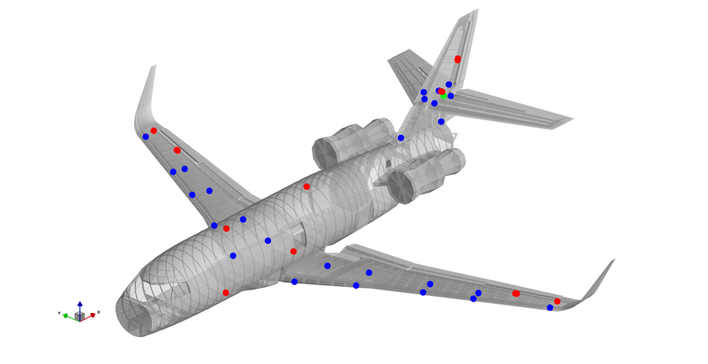
Figure 1: Positions and types of measuring points on the simulation model of the DLR research aircraft ISTAR
At all measuring points, 4 strain gauges are combined to form full bridges. Blue: Measuring point for bending moments. Green: Measuring point for shear forces. Red: Measuring point for tensile/compressive forces.
From November to December 2023, the "Strain Gauges Calibration" tests shown in Figure 2 were carried out on ISTAR. In addition to the experts from Dassault Aviation, employees from the DLR Flight Experiments in Braunschweig and scientists from the DLR Institute of Aeroelasticity were also involved. The loads applied during the calibration reached approx. 30% of the design loads (limit loads). For high quality results, the applied loads should almost reach the level of the loads expected in flight. Nevertheless, the loads should be low enough to minimize the risk of fatigue damage to the aircraft structure.
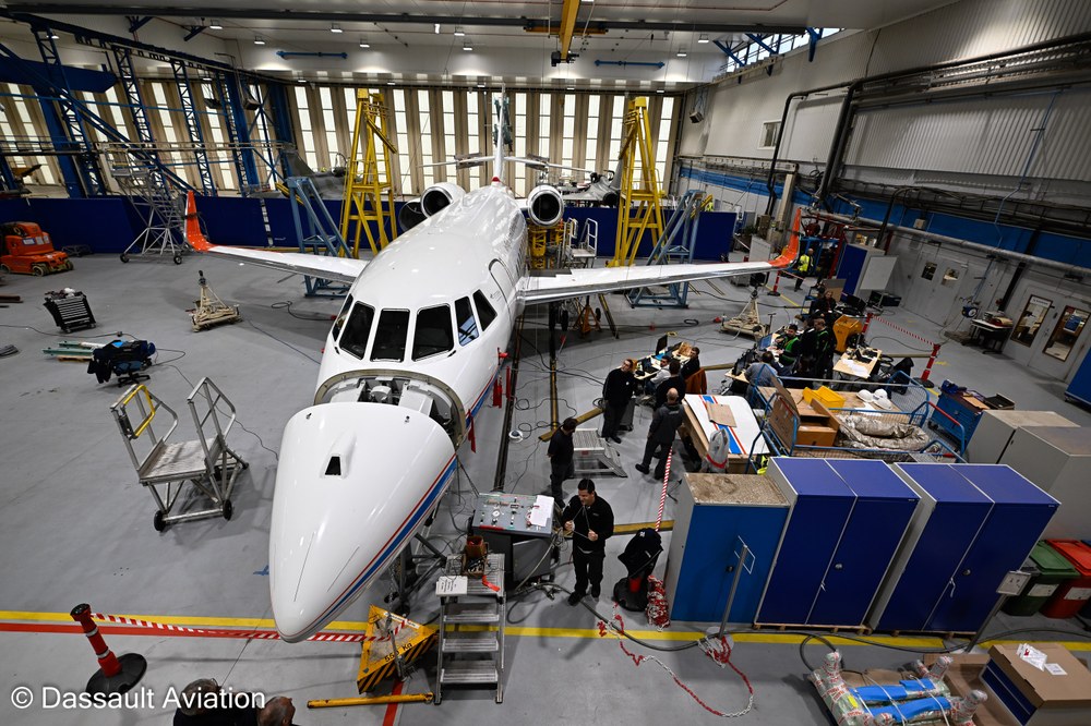
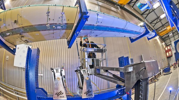
Figure 2: Strain Gauges Calibration Test on the DLR research aircraft ISTAR at Dassault Aviation in Istres
The aircraft manufacturer's infrastructure was used to calibrate the ISTAR instrumentation to identify flight loads.
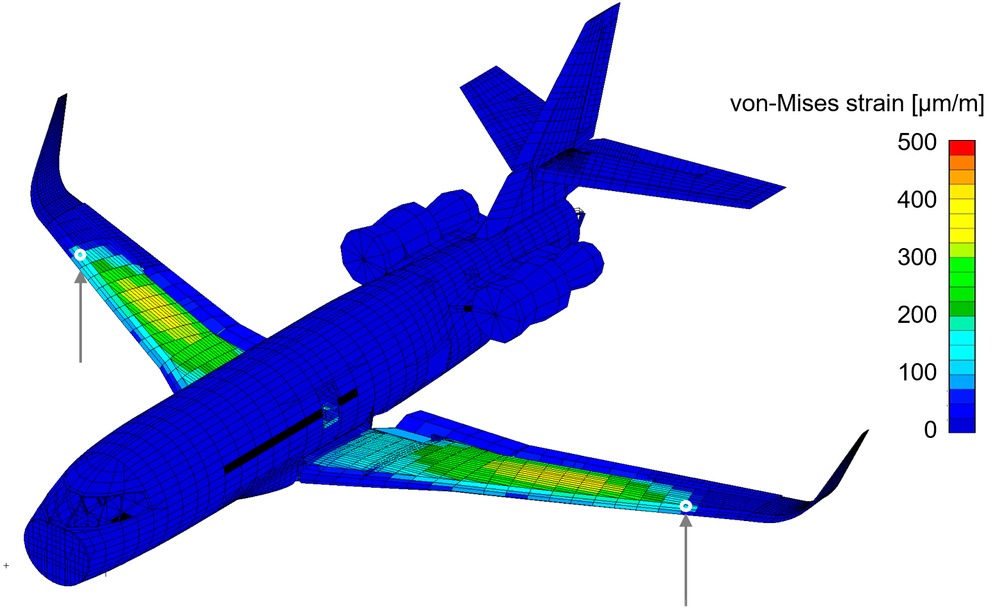
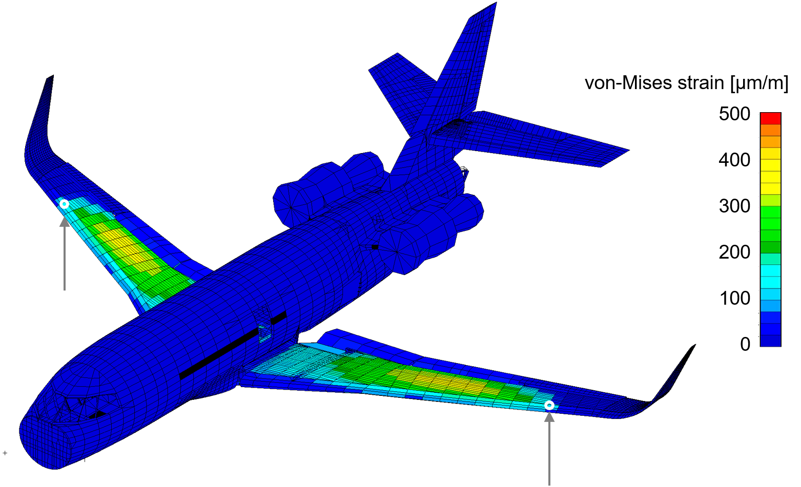
To plan the tests, all load cases were simulated in advance using a finite element model of ISTAR. Figure 3 shows the spatial distribution of the equivalent strain for a symmetrical load case on the front spar of the wings.
Figure 3: Finite element model of the DLR research aircraft ISTAR
Spatial distribution of the equivalent strain according to von-Mises for a symmetrical load case on the front spars in the positive vertical direction. The strains due to elastic deformation, which in this case are only limited to the wing, can be recognized.
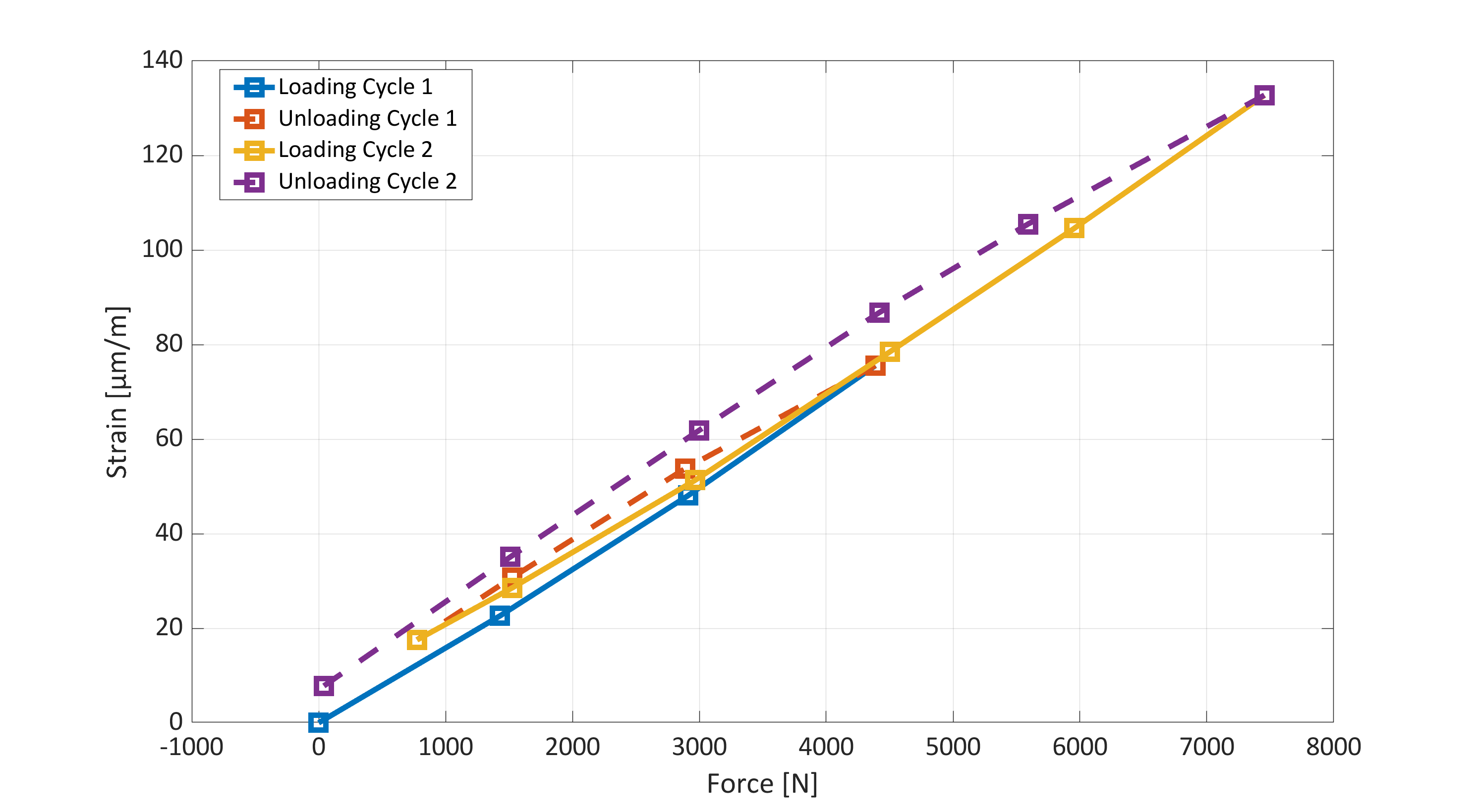
In order to avoid non-linear effects - e.g. hysteresis due to friction at riveted joints - two load cycles were applied in each load case. The first cycle only reaches approx. 60% of the desired maximum load. The undesirable hysteresis effects are expected to occur in this case. The second cycle is then run up to the desired maximum load, whereby the non-linear effects then only occur to a small extent.
When the loads were applied, the aircraft was jacked up at the jacking points. In addition, it was braced against the ground with chains at these points to prevent tilting during the load application.
Load cycles
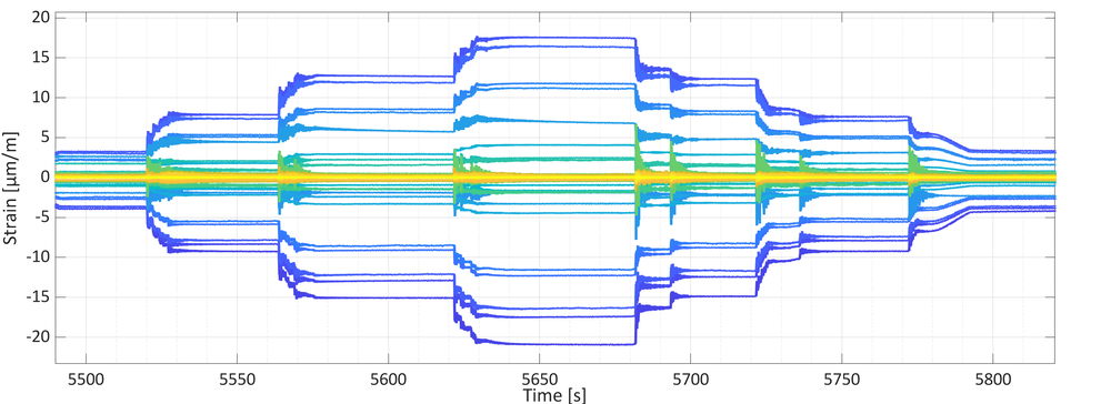
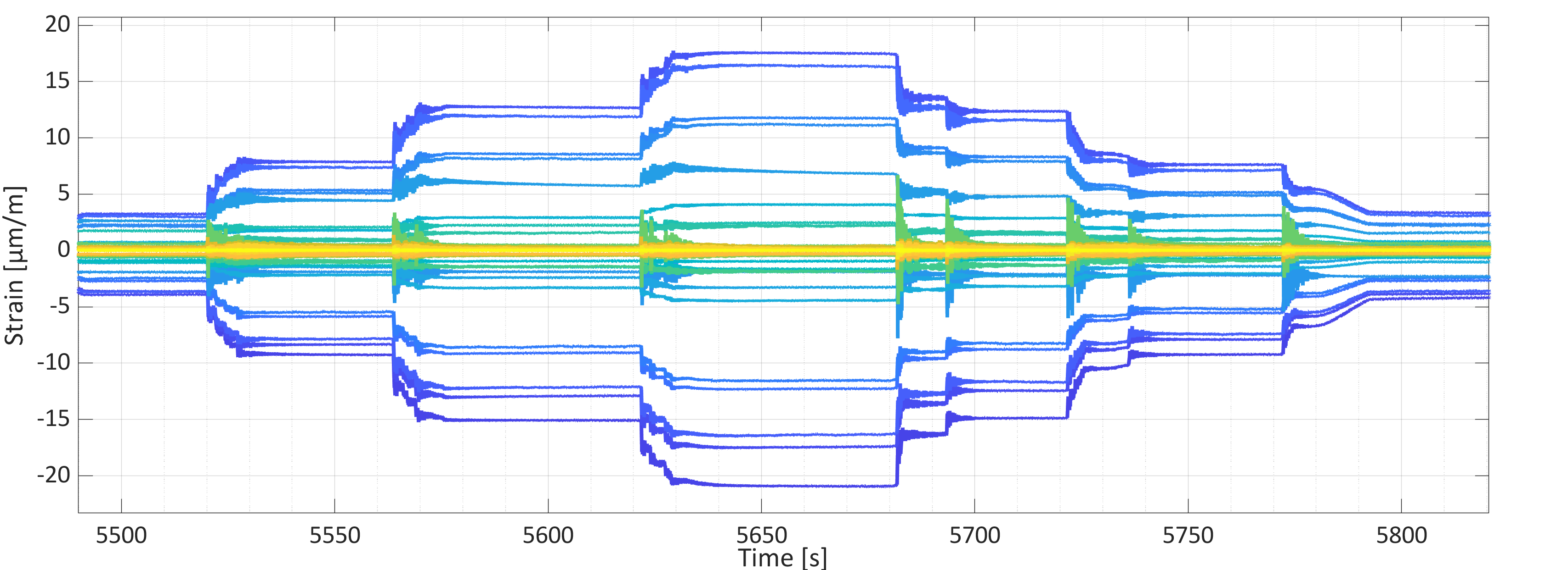
The loads were applied in 20% increments in both cycles. Hydraulic actuators equipped with static force sensors were used for this purpose. At the beginning of the first loading cycle, the signals from the instrumentation were tared (i.e. set to zero). The signals from all strain measurement points and the force sensors were then recorded without gaps until the end of the load cycle. This can be seen in Figure 4, for example.
Figure 4: Diagram - Calibration measurement on the DLR research aircraft ISTAR
Time histories of the signals from all strain measurement points. The gradual application of the load can be recognized. During the rest phases of the individual steps, data points were marked from which the results of the calibration measurement are compiled.
Distinctive and representative points in the measured strains and excitation forces were marked from time histories during the test. This allowed force-strain diagrams to be generated subsequently, see Figure 5.
Figure 5: Force-strain diagram ...
... for a measuring point from a load case. One can recognize the settlement movements that essentially take place during the first load cycle. The gradients of the force-strain diagrams are required for the Skopinski method.
The actuator rods of all control surfaces are also instrumented with strain gauges. These have already been calibrated in advance using a tensile machine from materials testing.
Benefits for future research
With this type of strain measurement, the loads acting on the aircraft can be observed over a long period of time in the future. This can be used to gain insights into structural fatigue and also, for example, to adapt aircraft maintenance intervals to the loads that have actually occurred.
Cause-and-effect relationships in flight loads can also be measured - starting with the deflection of the control surfaces, through internal loads in the wings and empennage, to maneuver accelerations. This allows the aeroelastic modelling of the flying and maneuvering aircraft to be improved.
Last but not least, the experimental determination of flight loads serves to create a virtual twin of the ISTAR research aircraft. The continuous improvement of the match between virtual and real product is part of DLR's aviation strategy.


