Flutter is a form of aeroelastic instability that manifests itself with oscillations (see Figure 1) which either grow, and eventually lead to a structural failure, or remain at some constant-amplitude provoking fatigue issues. Due to the safety implications of the phenomenon, design clearance from flutter must be guaranteed. Nowadays, this is assessed in advance using numerical calculation methods and, if the aircraft design shows a tendency to flutter, it must be modified. The result would be an heavier, less optimised airframe. A more appealing approach is the use of active technologies to deflect the aircraft’s flaps in such a manner that the oscillations are effectively damped. This concept is known as Active Flutter Suppression (AFS). However, the question arises whether this technology can be safely applied to any sort of fluttering aircraft?
An analogy through the inverted pendulum problem
While seemingly simple, the inverted pendulum problem shares many common features with the flutter suppression problem, offering a significant advantage: you, the reader, can try it yourself! The illustration is as follows: it is relatively easy to balance a long stick with your hand, whereas balancing a short stick might be challenging, and balancing a very short one is impossible. The explanation lays in the fact that the shorter is the stick the larger is the magnitude of its unstable pole, namely the short stick becomes more unstable. The more unstable is the system to be controlled, the faster the stabilizing action has to be delivered. However, the human body has many limitations, associated with perception and actuation of the limbs, therefore the more unstable sticks are impossible to be balanced [1].
Analogously to our limbs, the electro-hydraulic actuators that deflect the control surfaces have limited actuation rate and amplitude. Consequently, if the aircraft is highly unstable, flutter cannot be controlled. Additionally, if a gust tilts the stick from our above experiment significantly, it becomes difficult to return it to its vertical position. There is only a limited set of angles, or “states”, within which stabilization is possible. Similarly, in turbulent conditions, aircraft can only be stabilized within a limited set of states due to limited actuator rate. The identification of this set of states is crucial to assess the safe operability of the aircraft.
The controllable region, an unsurpassable boundary
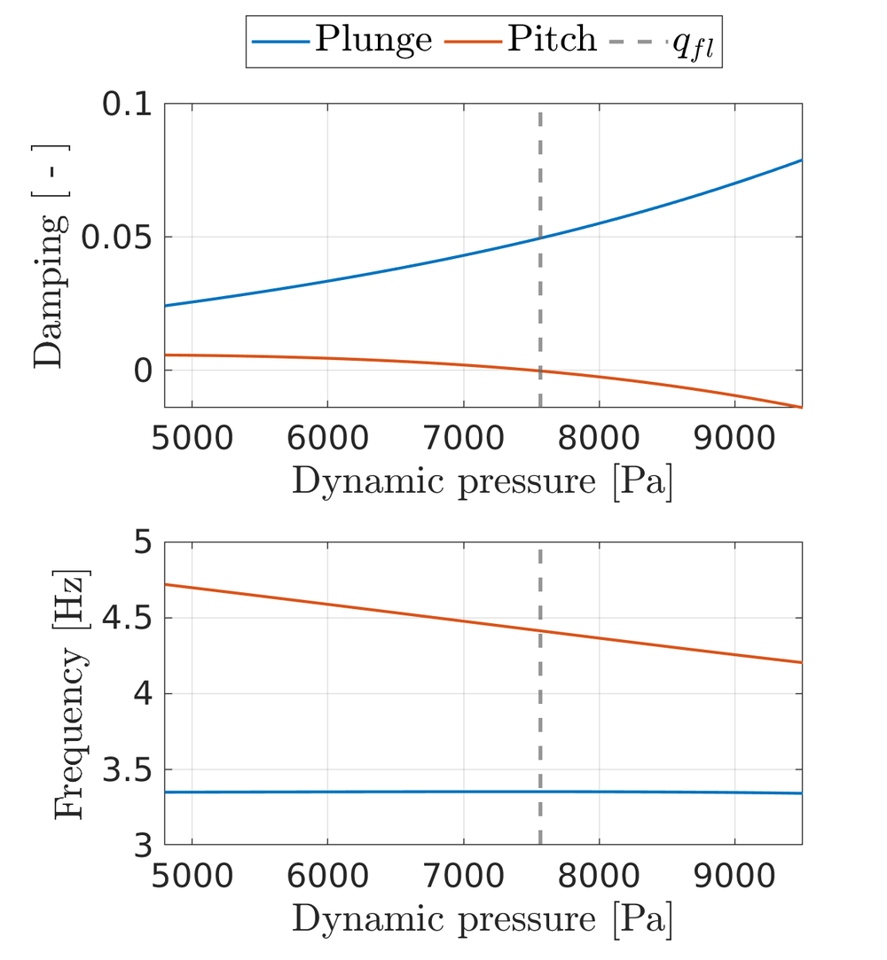
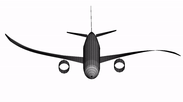
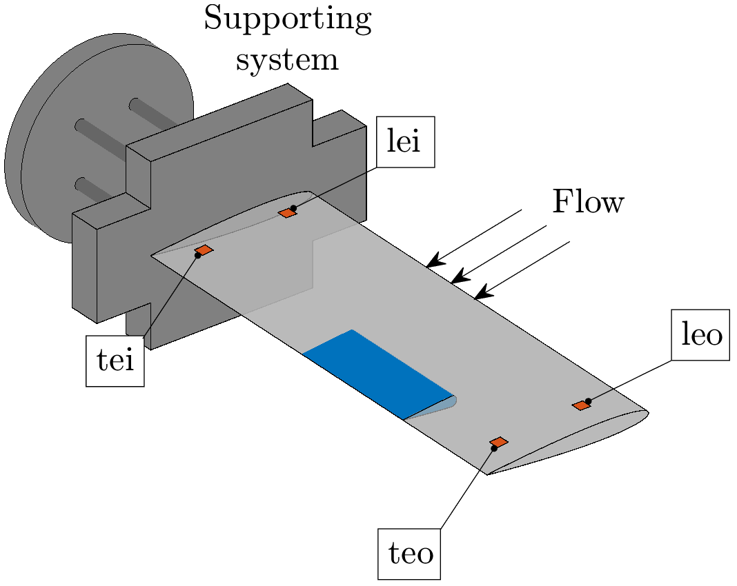
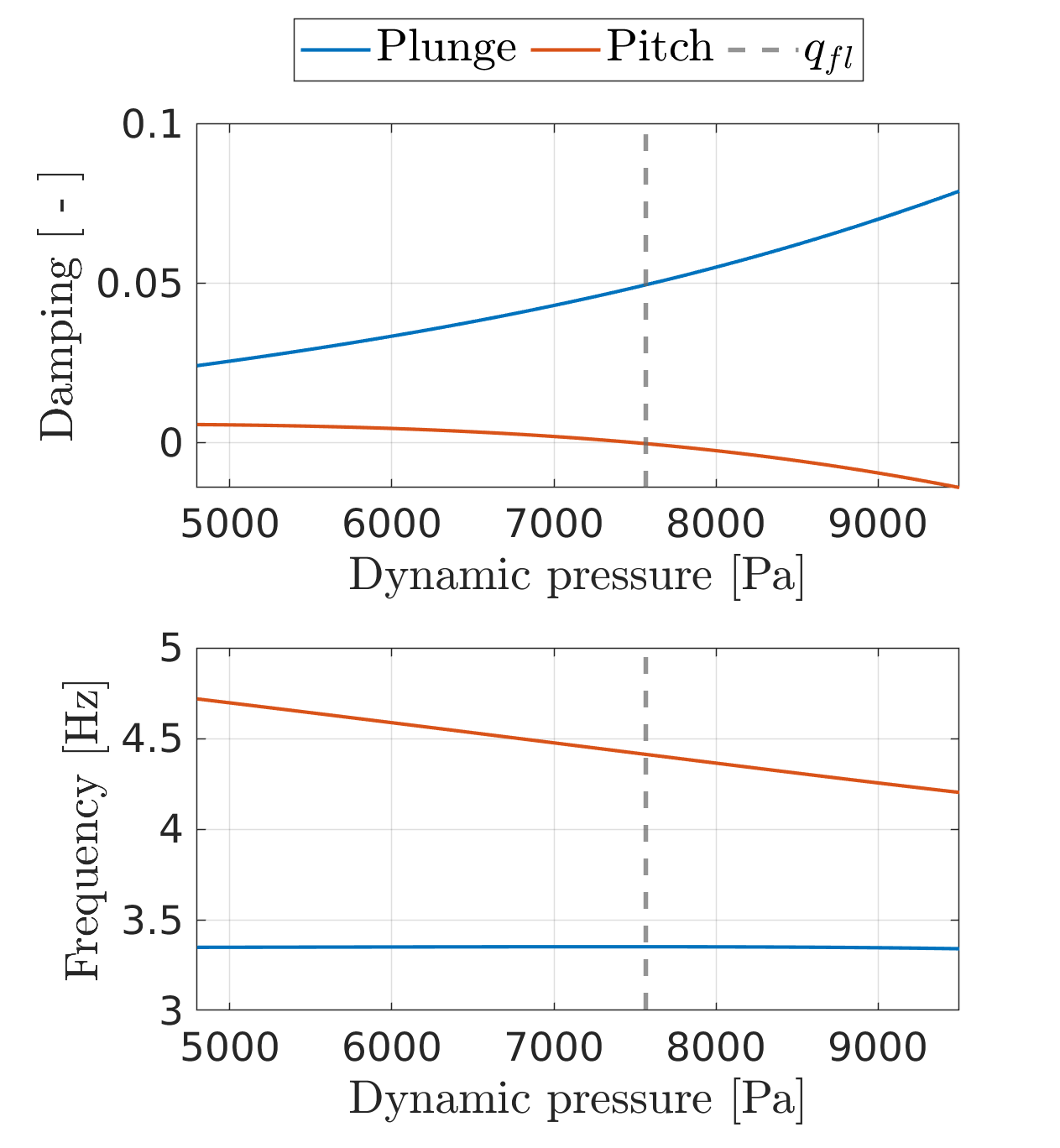
The set of states over which it is possible to perform a control action considering input constraints is known as the controllable region C [2]. This region is a function of the dynamic response of the aeroelastic system, along with the performance of the actuators employed to command the flaps that deliver the stabilizing action. An algorithm for the characterization of C was developed in [3] and demonstrated employing a numerical benchmark from NASA, the so-called BACT wing [4]. The BACT wing is mounted on a supporting system which enables the wing to plunge and pitch. Figure 2 illustrates the wing, whereas Figure 3 shows the evolution of its aeroelastic behavior with increasing dynamic pressure, that can be considered as a measure for the airspeed when the density of the air does not change.
Figure 2: BACT wing representation with the supporting system as well as the locations of accelerometers (red) and the trailing edge flap for flutter control (blue)
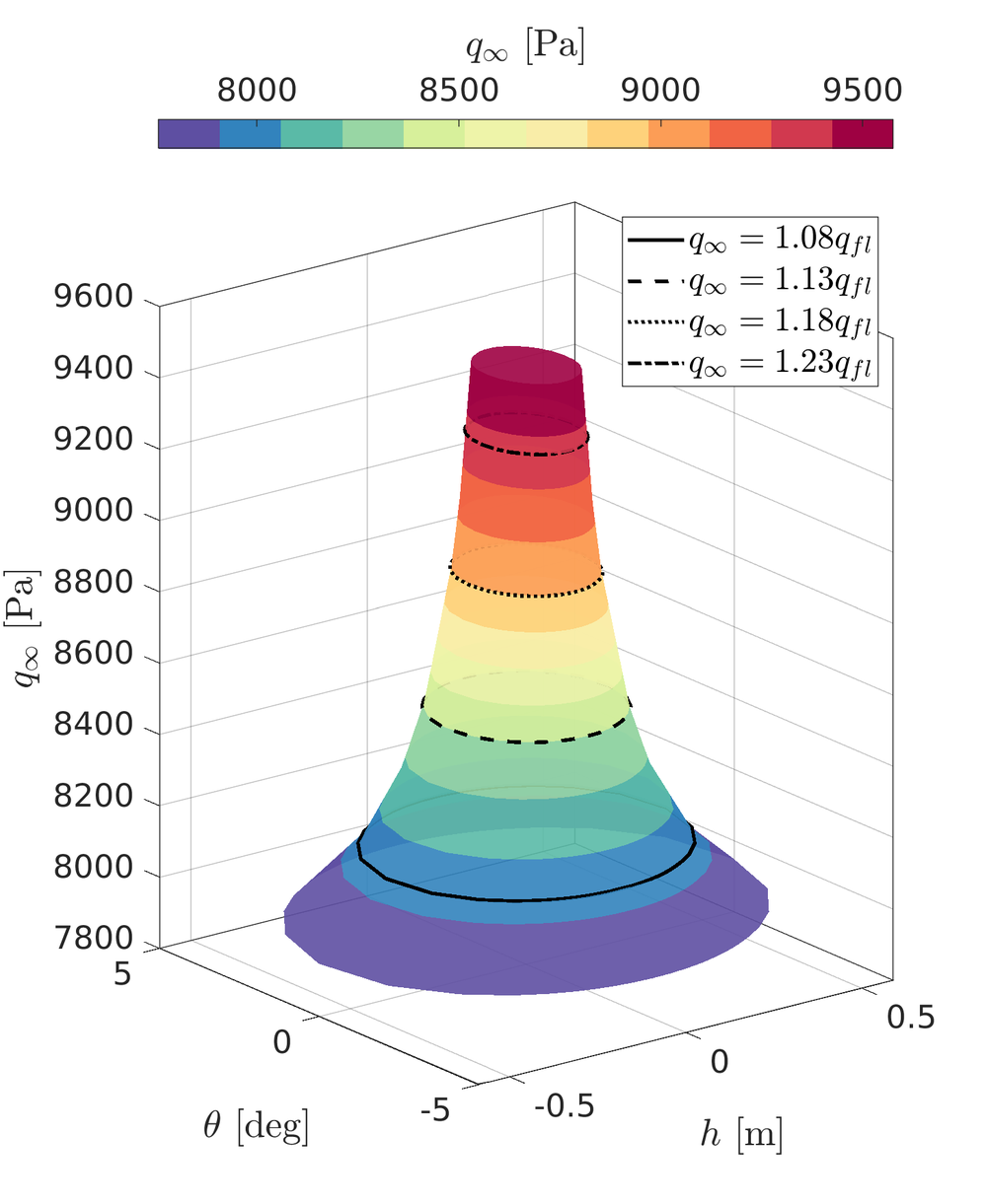
Specifically, the wing becomes increasingly more unstable as the dynamic pressure grows (notice the pitch mode whose damping becomes more negative). Assuming a maximum deflection of the flap of 10 deg and a maximum actuation rate of 50 deg/s, the algorithm is employed to compute the evolution of C beyond qfl. The results are illustrated in Figure 4 for plunge motion with vertical displacement h and pitch motion with angle θ. The figure clearly shows how the size of C plummets with increasing dynamic pressure, due to the increasing level of system instability. At 15% above the flutter dynamic pressure, the controllable region permits a maximum pitch motion of approximately 2 degrees. This implies that if a perturbation results in a pitch angle higher than 2 degrees, no sophisticated controller would be capable of stabilizing the wing, and oscillations would grow unbounded.
It becomes clear that the maximum value of achievable dynamic pressure when the servo loop (comprising sensors, flutter suppression controller, and actuators) is active depends on design decisions and safety considerations. These factors must consider the evolution of C. For a comprehensive illustrative example, refer to [3].
Figure 4: Evolution of controllable region cross section C (h,θ) of the BACT wing beyond q_fl


