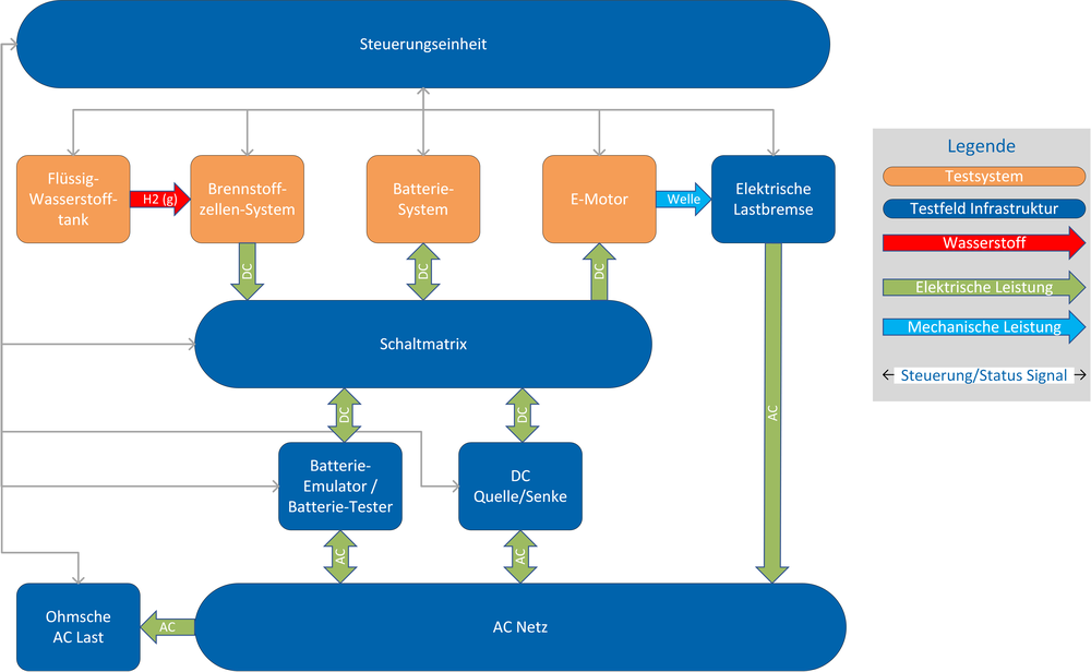
Flexible wiring is necessary so that the main components can be tested individually and in different combinations. The main components such as the fuel cell and battery system as well as the drive system with the inverters work with direct current. In order to be able to operate the components individually, three source/sink modules are available that either draw alternating current from the public power grid and convert it into direct current to supply the components or feed the direct current of the components into the power grid as alternating current.
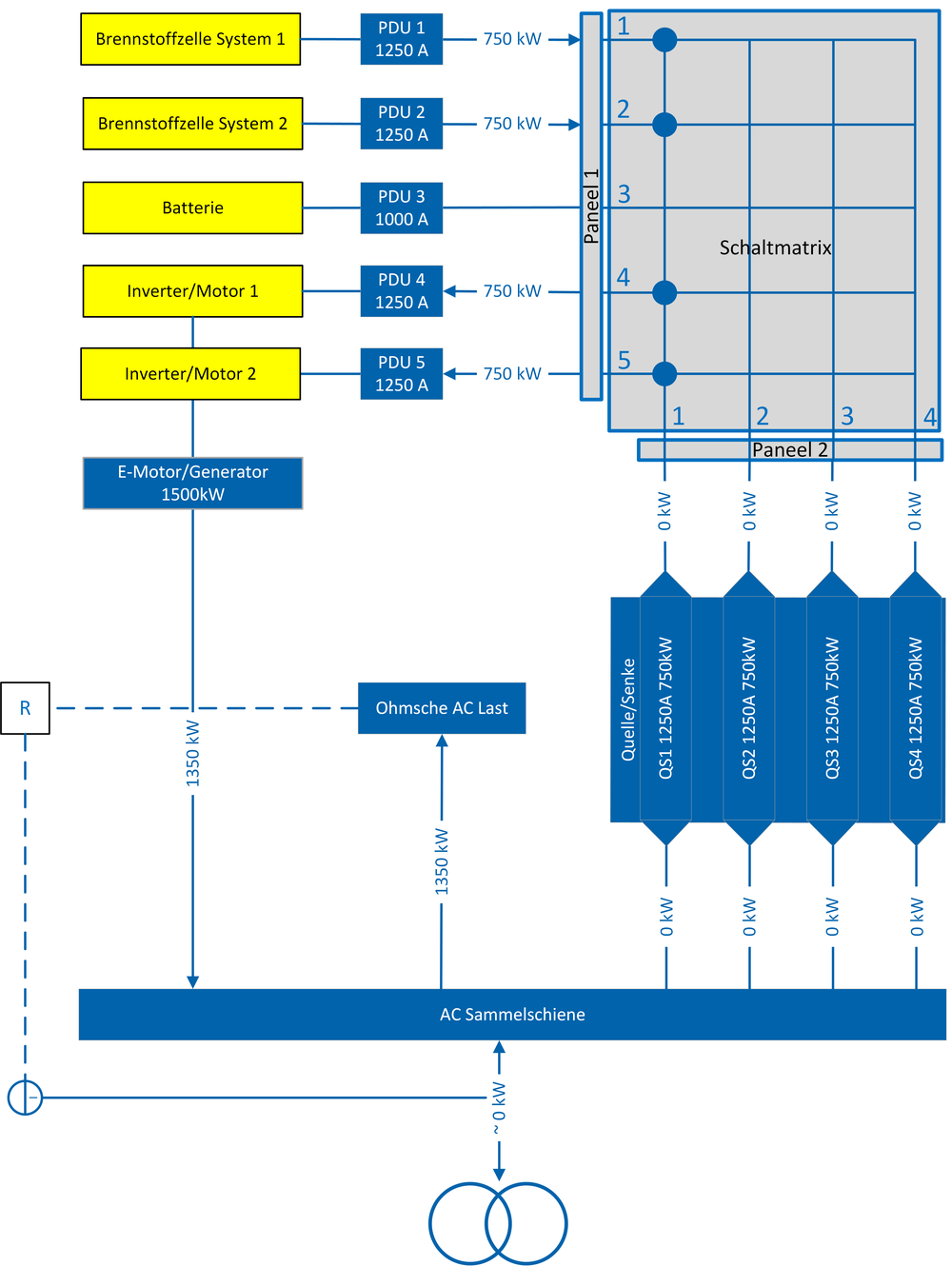
In addition to coupling with a real battery via the battery test field, it is also possible to simulate the behaviour of a battery using a battery emulator. A switching matrix is used to combine the components as required. This makes it possible to connect the components to each other, but also to the DC sources/sinks and the battery tester/emulator. An example circuit in which the two electric motors are fed directly from the fuel cell system is shown in Figure 1. High voltages of up to 1,200 V and high switching currents (greater than 1250 A) occur in the system, which the aviation-compliant high-performance switches and diodes must be able to handle. In addition to the conventional test stand control system, an aviation-certified control system is available so that the control system can be designed as closely as possible to a later application in the aviation sector.

