
Department
Aeroelastic Experiments
The department “Aeroelastic Experiments” is committed to the planning, realization and analysis of challenging experiments in wind tunnels.


From the beginning, Helicopters always have rotor blades with a simple rectangular planform. This worked and had proven as the typical helicopter rotor blade principle. But if the rotor blade planform will changed, rotor noise and vibrations can be significantly reduced, while enhancing the aerodynamic efficiency.
For this purpose a special shaped rotor blade planform with a kink [2] in the outer area were used, as already mentioned in the previous article [1]. So this leads to new challenges with respect to the aeroelastic behavior. Especially the relevance of dynamic stall is increasing in importance. The dynamic stall is an aerodynamic stall phenomenon, which occur on lift-generating frames during they undergoing fast and large changes of the angle of attack. This phenomenon occurs at helicopters during maneuvering and fast forward flight. More specifically, on the rotor blade that is moving backward just opposite to the direction of flight. The consequences of this phenomenon are high values in aerodynamic lift, drag and pitching moment. This yields to very high torsion- and bending moments on the rotor blades and at adjacent rotor head components.
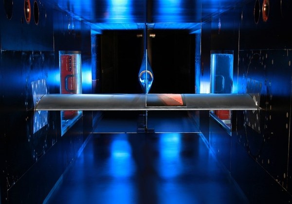
In general, the most aeroelastic experiments have a very complex experimental setup. The experimental investigation of helicopter rotor blade aeroelasticity add the challenge of measuring in a fast rotating rotor system. Here, the Rotor Test Facility Göttingen (RTG) of the helicopter department of the Institute of Aerodynamics and Flow Technology provide the opportunity to investigate the dynamic stall as well as the hover and light climb of a helicopter rotor, with respect to the aeroelastic behavior, see Figure 1. For this purpose, innovative rotor blades are mounted at the rotor head of the RTG and rotate with a constant frequency. In order to trigger the dynamic stall, the rotor blades undergoing a defined up-and-down movement once per revolution, i.e. an up-and-down rotation of the pitch or setting angle (dynamic measuring point). To represent hover flight or slight climb, a fixed pitch angle Θ, mentioned collective pitch angle, is set at the rotor blade clamping for all rotor blades (stationary measuring point).
Experiments and investigations using numerical flow simulation in the past, has shown the high aerodynamic complexity of the dynamic stall phenomenon. Meanwhile, effect mechanism of this phenomenon is well understood for two-dimensional flows [3,4]. In 3D, the complexity increased significantly from the aerodynamic point of view [5]. In rotor blade experiment, radial effects are added in addition to the increased three-dimensional complexity [6]. Therefore, different measurement techniques have to be combined to obtain a detailed insight in the aerodynamic and the structure behavior, for the aeroelastic investigation of rotor blades. The measurement techniques are used include strain gauges, optical marker tracking, fast respond unsteady pressure transducers, temperature sensors, unsteady pressure sensitive paint, 6-component balance and acceleration sensors, for more information see [7].
For rotor blades, it is common to plot the aerodynamic loads, structural deformations as well as the setting angle Θ over one rotor revolution or period, see Figure 2. Here, for a dynamic test case, it can be seen that the course of the aerodynamic load (green curve) and the structural deformation (blue curve), differs significantly to the course of the setting angle (red curve). If the structural deformation deviates so significantly from the setting angle curve, the rotor blade response can be described as non-linear (structural deformation). This can be observed in experiments and in aeroelastic simulations [7,8,9].

The answer of this non-linear behavior can be found in rotor blade aerodynamic. For this purpose, the global pressure distribution on the rotor blade surface is measured by pressure sensors and pressure-sensitive paint, seen in Figure 3. These data allow conclusions to be drawn of the aerodynamic behavior. In the case of the innovative rotor blade with a kink, it can be seen that the maximum lift will be reached before the maximum setting angle, see Figure 2. After that, the onset of stall can be observed at the backswept part of the rotor blade, see Figure 3. During the pitch-down motion, a reattachment of the flow at the backward swept part of the rotor blade can be seen. This leads to a renewed increase of lift and causes a renewed up bending of the rotor blade. All this happens before the minimum setting angle is reached, as shown in figures 2 and 3. Thus, the aerodynamic generated force has a time-delay to the defined upstroke and downstroke motion of the rotor blade, so the setting angle curve and rotor blade deformation deviate from each other.

Due to this deformation behavior, the rotor blade oscillates up and down once per rotor revolution. However, not simply up and down, as can be seen in Figure 2 (blue curve). To be more precise, this curve consist of two individual oscillations that overlap. One of them looks like the red curve in figure 2, the rotor blade oscillates once up and down. In the second oscillation component, the rotor blade oscillates up and down twice during one revolution. This behavior must be considered in the structural design and construction of rotor blades, especially since further aeroelastic challenges result from this behavior [1]. These aeroelastic issues associated with innovative rotor blades will be further investigated in future planned rotor tests on a scaled full-helicopter experiment in the DLR project URBAN Rescue with the innovative rotor blade in the Low Speed Wind Tunnel Braunschweig (NWB).
Martin, Michael Müller, DLR-Institute of Aeroelasticity, Department: Aeroelastic Experiments