
Formation Flying Testbed

Motivation
The use of GNSS sensors is widely spread in the design of spacecraft orbiting below the GNSS constellations. They provide accurate 3D position information in real-time and are thus natural candidates to serve the needs of spacecraft guidance, navigation and control (GNC). In addition the GNSS observables can be processed post-facto for very precise orbit restitution. However the utilization of GNSS sensors is not trivial and their behavior might be difficult to model, which justifies the need of hardware-in-the-loop test facilities. A GNSS receiver processes only radiofrequency waves sent by a constellation of satellites to derive the position and velocity information. As a consequence it is possible to recreate the physical environment measured by the sensor with a dedicated device, called GNSS signal simulator. The use of a GNSS signal simulator is of great interest for the design of test facilities with a high degree of realism. It becomes possible to use the true hardware sensor in flight conditions and to connect it directly to the computer on which the flight software is running. The flight software implements the sophisticated GNC algorithms to be tested whose control actions are fed back to the simulation environment. A real-time hardware-in-the-loop, closed-loop testbed is of relevance for advanced functional and performance test. The use of the real receiver in the loop ensures that the flight software is able to interface properly the sensor and to handle the failures that may occur. Ultimate assessment of navigation, guidance and control performances is achieved by avoiding any software model of the sensor. Furthermore the introduction of a target computer representative of the onboard micropocessor on which the flight software is running may serve as support for software resource usage analysis. The Formation Flying Testbed developed at GSOC is intended to support the design, implementation, testing and validation of real-time embedded GPS-based GNC systems. It allows the definition of complex scenarios involving up to 2 spacecraft and equipped with L1- GPS receivers.
System Architecture
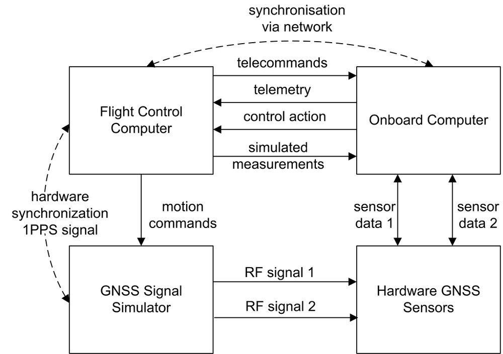
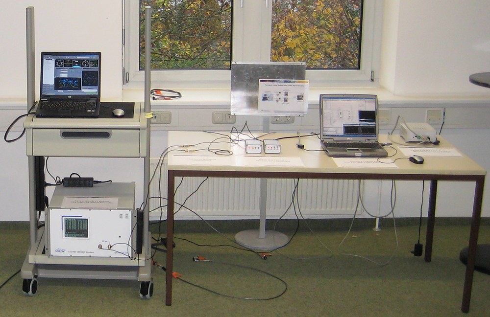
The Formation Flying Testbed is a mission-independent test facility. As such it is designed to offer a high flexibility in order to be utilizable for a large variety of mission profiles. Focus has been given to the simplicity and transparency of utilization to ensure the durability of the project. To that end the complete simulation environment is implemented using Simulink, which offers a user-friendly interface, a high modularity and is usually well-known among the aerospace community. Furthermore it makes the complete system easily upgradeable and extendable. Dedicated sophisticated user-defined Simulink blocks have been developed using C++ based S-functions to support the steering of the system and the communication between components. The system comprises four logical units (cf. Fig. 2):
- Flight Control Computer (FCC): model-based Simulink application that simulates the spacecraft dynamics and characteristics. It computes the transational and rotational motion of the spacecraft using precise force modeling and including the control actions sent by the GNC flight software. Furthermore it comprises accurate models of the spacecraft actuators and additional sensors. The FCC steers the GNSS signal simulator by providing motion commands in real-time. Complex scenarios are built using time-dependent events. A simplified emulation of the ground segment is also available to send telecommands and receive telemetry data.
- GNSS Signal Simulator (GSS): device used to simulate the radiofrequency signals output of the GNSS antenna of the spacecraft. It takes as input the translational and rotational motion of the spacecraft sent by the FCC. Additional parameters can be tuned to improve the realism of the scenario: description of the GPS constellation, atmosphere model, antenna characteristics.
- Hardware GNSS Sensors: receivers used to process the radiofrequency signals out of the GSS and feed the onboard computer with measurements.
- Onboard Computer (OBC): device on which the GNC flight software is running. The control actions are sent in real-time to the FCC. Depending on the maturity of the GNC prototype to be tested, the OBC can be for example a x86 architecture running a Simulink model or a SPARC architecture running C/C++ flight software compiled for a real-time operating system.
Further Reading
Ardaens J.-S., D'Amico S.;
Formation Flying Testbed;
DLR-GSOC TN 09-01; Deutsches Zentrum für Luft- und Raumfahrt, Oberpfaffenhofen (2009).
Ardaens J.-S., D'Amico S.;
Spaceborne Autonomous Relative Control System for Dual Satellite Formations;
Submitted to: Journal of Guidance, Control and Dynamics (2009).
Yamamoto T., D'Amico S.;
Hardware-in-the-loop Demonstration of GPS-Based Autonomous Formation Flying;
4th ESA Workshop on Satellite Navigation User Equipment Technologies, NAVITEC'2008, 10-12 December 2006, Noordwijk (2008).