The electronic components of the mechatronic running gear

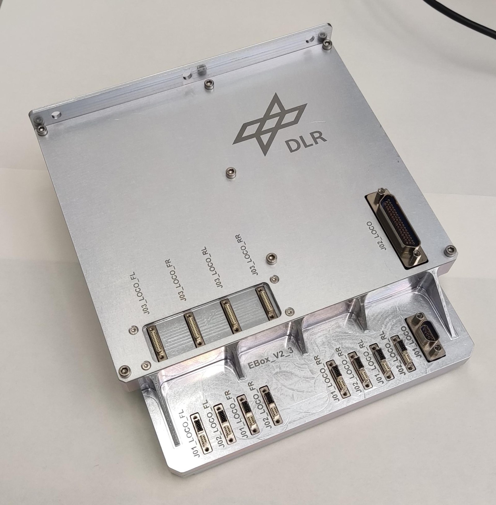
A central component in the MMX rover's mechatronic running gear is the electronics box developed by the DLR Robotics and Mechatronics Center. This box contains the analogue and digital circuits required to operate the rover. Essential sub-tasks are fulfilled by the measurement equipment, the power electronics and the communications unit. The measurement equipment collects and digitises the signals from the various sensors present in the locomotion system. With their help, motor currents, torques, joint positions, temperatures, accelerations and rotation rates are recorded.
The power electronics control the motors for the shoulder joints and wheels. The electronics box communicates with the higher-level on-board computer via a SpaceWire interface and thus makes the mechatronic chassis accessible to the overall rover system. All functions within the electronics box are controlled by firmware running on a programmable integrated circuit with logic functions (Field Programmable Gate Array; FPGA). All data from sensors, actuators that convert signals into mechanical movement, and communications come together in this core component.
The electronics box is the interface between the software that controls the rover and the physical interaction with the environment that takes place through the mechanical chassis components as well as the sensors. The rover's Power Control and Distribution Unit (PCDU) supplies power to the locomotion system's electronics box.
Extreme environmental conditions for the rover
To be able to operate the locomotion electronics safely and reliably during the rover’s entire lifetime, some challenging conditions have had to be taken into account during the design. The rover has to withstand extreme environmental conditions both during the flight and during its mission on the martian moon Phobos. In particular, very high and very low temperatures occur, and the change between these extremes is very rapid. Even spaceflight-qualified electronic components would not be able to operate reliably under these conditions. For this reason, all electronic components are combined as far as possible in the electronics box, which is housed in the rover’s thermally insulated interior.
Thermal insulation and a demand-controlled heating system can limit the thermal loads to a level that allows the safe operation of the components. Furthermore, in the thermal design of the electronics, care had to be taken to ensure that no heat exchange takes place through flow transport, due to the lack of atmosphere. In particular, components in which a lot of energy is converted, such as motor drivers and FPGAs, must therefore be connected in such a way that sufficient heat dissipation can take place via heat conduction and radiation.
In order to be able to cope with the cosmic radiation expected during flight and deployment on Phobos without damage, the design is based on a Total Ionizing Dose (TID) of 10 kilorads. Where available, suitably qualified components were used for this purpose. However, certain commercial components had to be qualified for use through tests. For the mechanical construction of the printed circuit boards and the electronics box housing, on the one hand, the vibration loads that occur above all during rocket launches had to be taken into account. On the other hand, the system could not be too heavy. For operation, the electronics were designed to have the lowest power consumption possible. Particularly during the deployment phase, the rover is solely dependent on power from the battery it carries. Only then can the solar panels be deployed. Last but not least, the mechatronic running gear must also be electromagnetically compatible with the other subsystems to ensure safe and trouble-free operation of the rover.
Safe operation in every situation
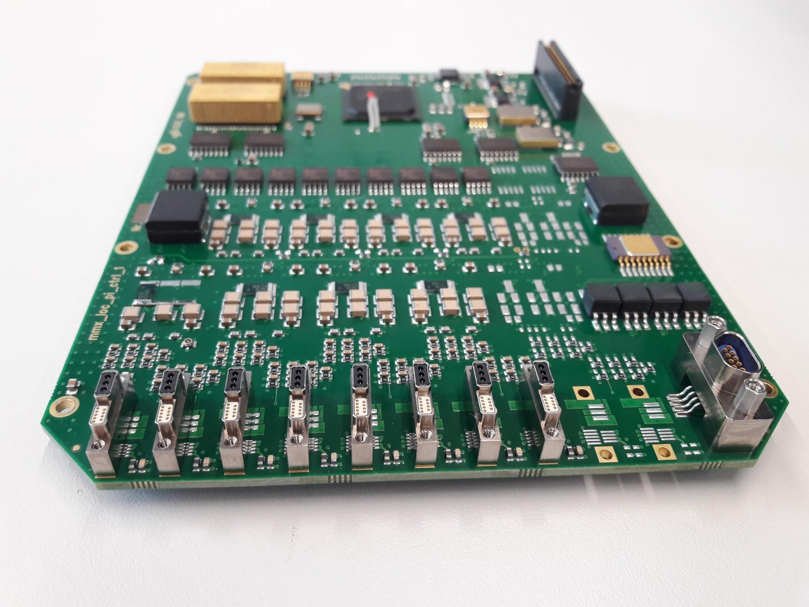
The main task of the locomotion electronics is the synchronous operation of all the motors in the wheels and shoulder joints for raising, driving and positioning the rover. Integrated motor driver modules are used for this purpose. The motors are controlled and monitored with the help of Hall sensors. In the event of a sensor failure, however, controlled operation of the motors is still possible.
A current monitoring system ensures the safe operation of the motors. Position sensors based on potentiometers and torque sensors based on strain gauges are integrated into the shoulder joints. The analogue output voltages of these sensors are fed to the electronics box. There they are amplified, filtered and digitised with the help of analogue to digital converters (A/D converters) for further processing in the control system. In addition, there is a three-axis acceleration sensor in each shoulder for recording the landing process. The analogue acceleration signals are also digitised by the A/D converters in the electronics box. A magnetoelectric memory is available for offline recording of the acceleration data during the entire landing process.
When a communication link is established after the rover is upright, this data can then be transmitted to the orbiter and provide information about the surface conditions on Phobos. The uprighting process is supported by the angular rate sensors integrated in the electronics box. Temperature sensors monitor the permissible temperature range both in the shoulders and at critical points in the electronics box. Heating elements keep the components within their permitted temperature range and bring them up to operating temperature if necessary. Individual sub-components of the electronics can be switched on and off as needed to minimise energy consumption.
Extensive tests for all electronic components
Numerous qualification and acceptance tests were carried out to verify compliance with the requirements. First, a ‘burn-in’ test lasting several days at maximum temperature was carried out with the electronics box. This ensures the timely detection of already damaged components that could lead to early failures. The thermal and mechanical resilience of the electronics box was proven in thermal vacuum and vibration tests. Electromagnetic compatibility tests verified that the electronics are resistant to the expected external interference and do not emit interference that would affect the function of other subsystems on the rover. In order to prove the required performance, functional tests were repeatedly carried out at the beginning and end of the test campaign as well as between tests.
MMX – Martian Moons eXploration
MMX is a mission of the Japanese space agency JAXA with contributions from NASA, ESA, CNES (the French space agency) and DLR. CNES (Centre National d'Études Spatiales) and the German Aerospace Center (Deutsches Zentrum für Luft- und Raumfahrt; DLR) are jointly contributing a 25-kilogram rover to the Martian Moons eXploration Mission (MMX). The Franco-German MMX rover is being designed and built under the joint leadership of CNES and DLR. In particular, DLR is responsible for the development of the rover's landing gear, including the lightweight body, as well as the entire uprighting and locomotion system. DLR is also contributing the connection adapter to the MMX spacecraft and providing a Raman spectrometer and a radiometer as scientific experiments. These will analyse the surface composition and texture on Phobos. CNES is making significant contributions with camera systems for spatial orientation and exploration on the surface, as well as for the study of mechanical soil properties. CNES is also developing the rover's central service module, including the on-board computer and the power and communications system. After the launch of the MMX mission, the rover will be operated by CNES control centres in Toulouse (France) and DLR in Cologne (Germany).
For DLR, the institutes of System Dynamics and Control, Composite Structures and Adaptive Systems, of Space Systems, of Optical Sensor Systems, of Planetary Research, for Software Technology and the Microgravity User Support Center (MUSC) are also involved under the leadership of the DLR Institute of Robotics and Mechatronics.
The MMX mission is a continuation of an already long-standing successful cooperation between JAXA, CNES and DLR. It builds on the previous mission Hayabusa2, in which JAXA sent a spacecraft to the asteroid Ryugu with the German-French MASCOT lander on board. On 3 October 2018, MASCOT landed on Ryugu and sent spectacular images of a landscape ridden with boulders and rocks, and virtually no dust. Hayabusa2 collected samples from Ryugu and brought them to Earth on 6 December 2020.