The chassis and connecting structure of the IDEFIX rover
MMX
The chassis and connecting structure of the IDEFIX rover
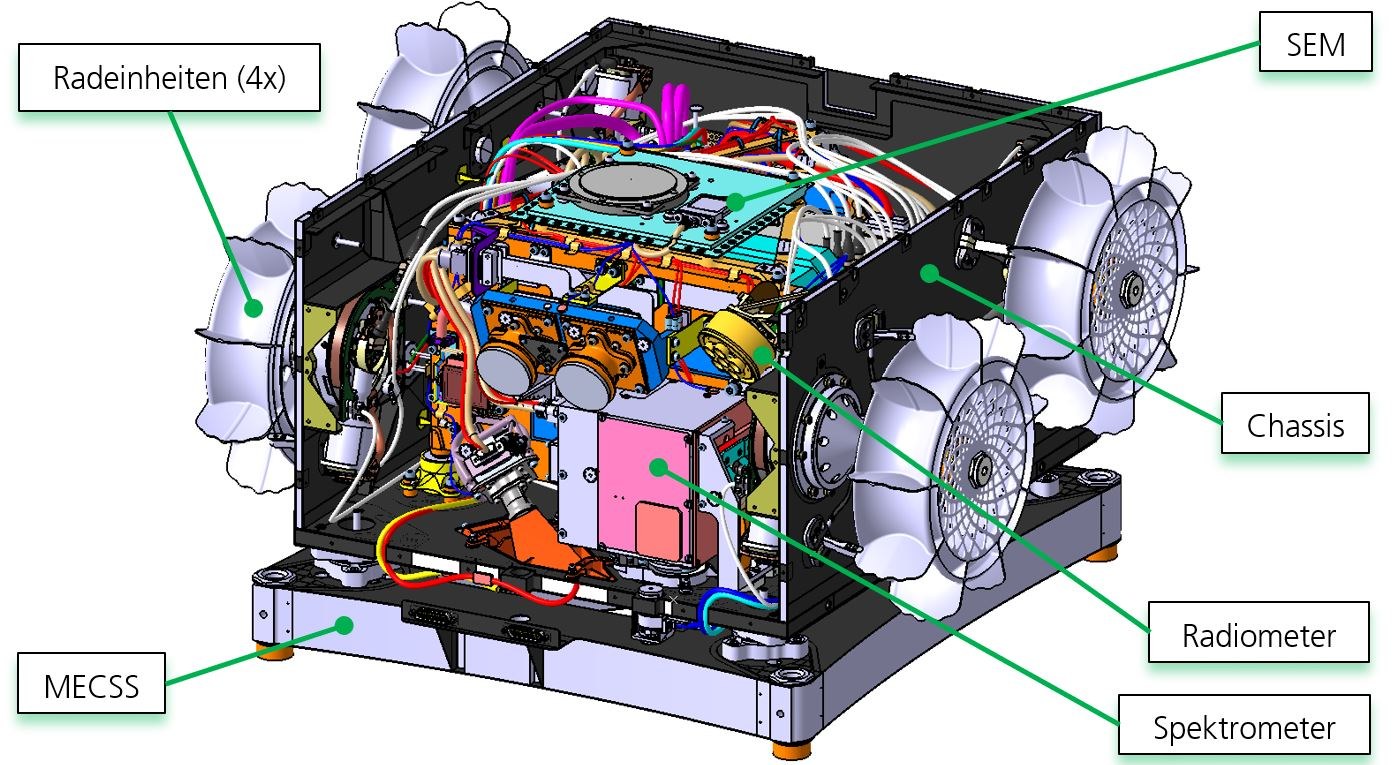
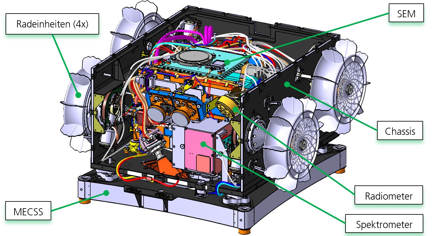
CAD model of rover and MECSS
Clockwise: SEM (Service Module, light blue), chassis (black), radiometer (yellow), Raman spectrometer (magenta), MECSS (Mechanical-Electrical-Communication and Separation System, purple) and the four wheels (purple). Front and cover plate with solar arrays and insulation foils are not shown.
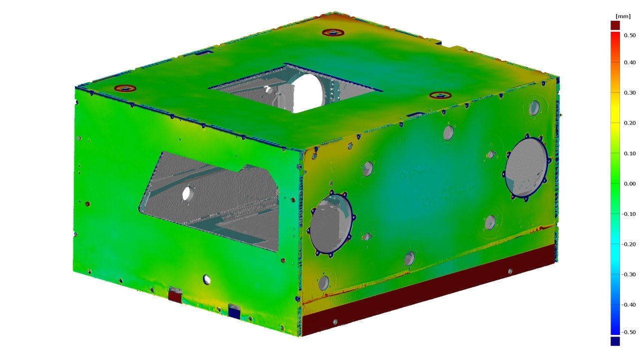
The image shows a measurement result of the chassis flight unit to check the surface evenness after the removable components (front, rear and cover plates) are fitted to the main chassis structure.
Travelling – driving – exploring … what initially sounds like a holiday to many people is also the cornerstone of the development of the MMX rover 'IDEFIX' and its supporting structure. In addition to the rover with the chassis structure, there is also the Mechanical-Electrical-Communication and Separation System (MECSS). This connects the rover with the MMX mother spacecraft during the launch and flight phases and is the communications system and lifeline of the rover during this period. Both structures were developed and constructed at the DLR Institute of Lightweight Systems in Braunschweig.
Nothing left to chance
The mission of the MMX rover is the scientific exploration of the surface of the martian moon Phobos and the technological demonstration of manoeuvring in a very low gravity environment. In addition, the MMX mother spacecraft will use the data obtained by the rover to calibrate its instruments and for its own landing preparations.
Over 70 technical requirements are derived from the mission objectives and environments, which directly influence the design of the structure. In addition, there is a large general set of rules (European Cooperation for Space Standardization; ECSS) that defines the quality control and product assurance processes as well as the standard test procedures. Technically, the chassis and MECSS should be able to do the following, for example:
The chassis, that is the supporting structure of the rover, must connect the SErvice Module (SEM) instrument carrier system and the radiometer instrument with the externally mounted wheel units and solar generators to form a single unit.
The maximum launch mass of the rover is limited to 24.85 kilograms and the installation space is limited by several neighbouring instruments on the exploration platform of the MMX probe. When separating from the mother spacecraft or the MECSS connection structure, the rover must not leave a defined corridor.
The stiffness, a measure of the structure's resistance to deformation under load, must achieve a minimum eigenfrequency in excess of 120 Hertz for the entire system.
During the rocket launch, accelerations of up to 28 g – 28 times the acceleration due to gravity – act on the rover. The structure must be able to withstand this stress without sustaining any damage. As the landing on Phobos is ballistic, similar to throwing a die, it must be possible to absorb the energy of the landing impact without damaging other parts of the rover. This was already successfully tested with drop tests during an early development phase.
Systematic lightweight construction
The structure of the 2.96-kilogram rover chassis consists of more than 160 individual parts bonded together. On the one hand, these form the basic chassis structure, consisting of the base plate, left- and right-side panels. On the other hand, separate and removable front, rear and top panels complete the basic chassis structure to form a closed box. The individual panels are each constructed with a sandwich design, which means that their basic structure consists of two external CFRP cover layers, which are separated by an aluminium honeycomb core. This construction method keeps the structural mass very low and maximises rigidity at the same time.
However, as high local loads act on the structure, particularly during launch and landing, further technical measures are required. For this purpose, the structure has inserts made of carbon-fibre-reinforced plastic (CF-PEEK), which fill the voids in the aluminium honeycomb cores. The inserts work in a similar manner to a dowel and allow components, such as the wheel units, to be bolted to the sandwich structure.
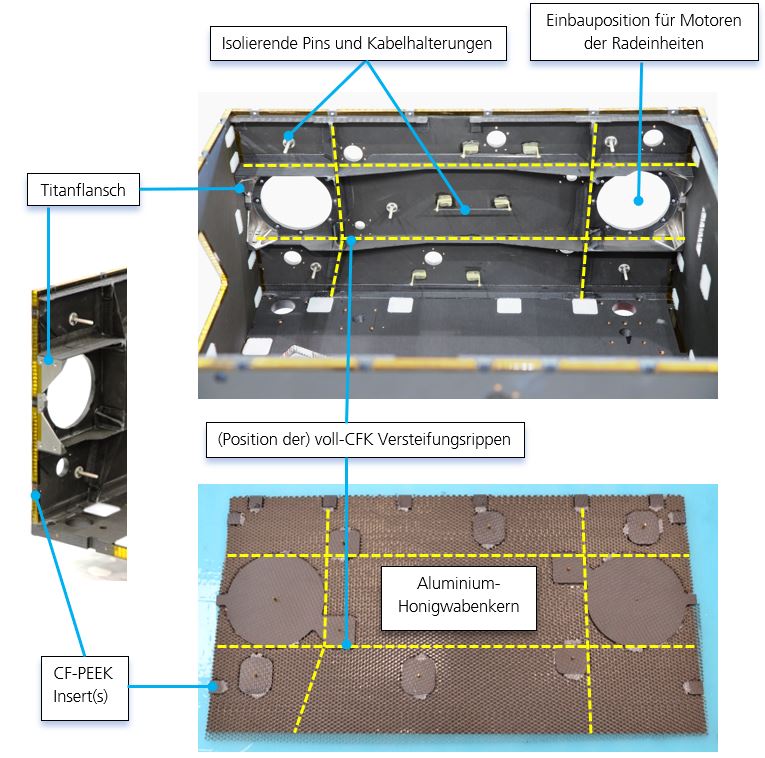
The structure of the rover chassis
Image left – view of the front edges of the right-hand sandwich side panel of the chassis with CF-PEEK inserts and a titanium flange. The aluminium honeycomb core visible in this view is covered with amber-coloured polyimide film. Image top – chassis interior with stiffening ribs, thermally insulating pins and cable retainers on the right-hand side panel. Image bottom – view into the sandwich panel of the right-hand side wall during production. The CF-PEEK inserts, which locally replace the aluminium honeycomb core, can be seen. The upper CFRP layer has not yet been glued on, and the machining for holes / threads etc. in the inserts is still to be performed.
Additional stiffening ribs made of carbon fibre reinforced plastic (all CFRP) and titanium flanges are used to transfer the loads applied to the inserts. The ribs are attached to the inside of the sandwich walls in such a way that they can absorb the loads from the inserts and then distribute them more widely. The titanium flanges transfer the loads to the front and rear walls of the chassis and offer additional mountning options in the very confined installation space directly next to the internal motors of the wheel units.
The biggest technological challenge with the chassis was the design and construction of the cover plate, which has to remain dimensionally stable over a temperature range of minus 145 to plus 75 degrees Celsius. From an electrical point of view, all components of the cover plate – with the exception of the top layer – must be electrically connected to each other. However, electrical insulation is required from the rest of the chassis. All the more remarkable is the extremely lightweight character of the 324-gram cover plate. This is because it carries the entire solar generator and its associated electronics, which together make up approximately 16 percent of the rover's total mass.
'Hot and cold' to Phobos
During the flight and on Phobos, the structure will be exposed to extreme temperature fluctuations. This will result in thermal stresses that could lead to cracks in the material or warping. One advantage of CFRP is that it expands and contracts only slightly under the influence of temperature. Although the effect is greater with the titanium flanges, it is still manageable. In order to be compatible with add-on parts that have a higher coefficient of thermal expansion, special solutions are required for the interfaces; for example, particularly elastic adhesives. The techniques used require many manual work steps, which posed challenges for even the most experienced technical staff.
The motors of the wheel units and the scientific instruments inside the rover must also be protected from the harsh environmental conditions. In addition to the material used, this is ensured by the sophisticated arrangement of thermal isolators between the chassis structure and the components attached to it. The best possible compromise between the sub-disciplines of structural engineering, thermal design and robotics was found through the joint creation of designs and subsequent simulations and tests with the support of the integration teams.
Several layers of insulating foil are installed between the outer chassis wall and the central instrument carrier system of the service module, which was developed by CNES. The foil has been attached to special thermally insulating pins so that it touches the particularly cold areas of the chassis as little as possible. For the same reason, the mounting of the main cable harness on the side wall of the rover is also made of particularly good insulating material – aramid and glass fibre. This prevents the exchange of thermal radiation as far as possible and maintains a stable separation between the outer 'cold' and inner 'warm' areas. Inspired by a design that has already been successfully used on the Philae lander, proven technologies have been adopted here. In this way, the development and testing effort was significantly reduced
Solutions for the separation and landing phase
The second main structure developed and built at the Institute of Lightweight Systems is that of the Mechanical-Electrical-Communication and Separation System (MECSS). This also consists of a sandwich construction, but with a significantly thicker aluminium honeycomb core than that of the chassis. This gives the MECSS structure extremely high flexural rigidity, which is particularly necessary during the launch phase.
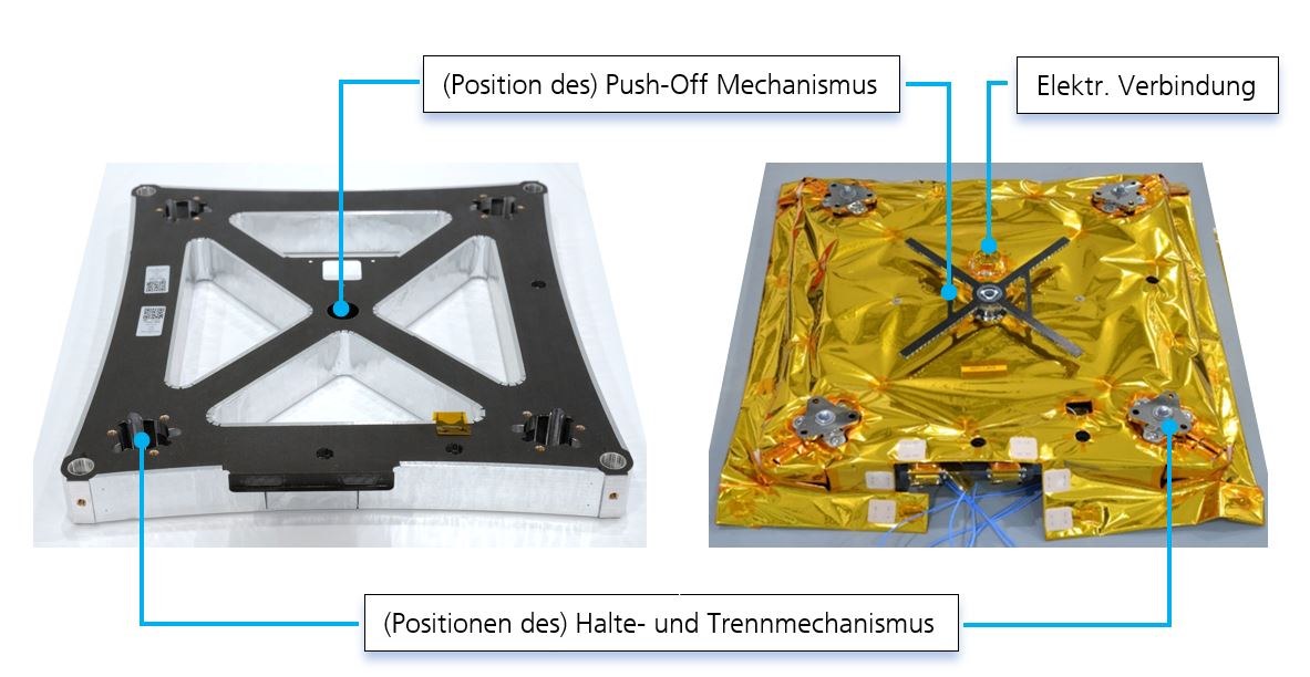
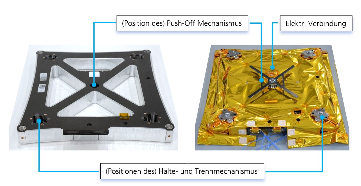
The structure of the Mechanical-Electrical-Communication and Separation System (MECSS)
The 40-millimetre-thick aluminium honeycomb core is covered with aluminium adhesive tape (left), while the fully integrated MECSS with holding and separating mechanism, electrical connector, push-off mechanism and external insulation foil can be seen on the right.
The unusual-looking geometry of the CFRP sandwich construction is partly due to the separation system integrated into the MECSS. This consists of an electrically redundant hold-down and separation mechanism with detachable bolts in each of the four corners. This means that the rover and MECSS are firmly connected to the mother spacecraft during the liftoff and flight phases. Only when landing is initiated are the bolts released simultaneously in response to a command. The push-off mechanism in the MECSS then propels the rover away. This mechanism, also developed at the Institute of Lightweight Systems, is based on a similar system that was successfully used for MASCOT. The functional principle is that a spring expands when the bolts are released, accelerating the rover to a speed of approximately 20 centimetres per second. The push-off process will also disconnect the electrical connections between the rover and the mother spacecraft. The rover will then be in free fall towards Phobos. After the rover has landed and the solar arrays have been unfolded and deployed, the scientific part of the mission will begin.
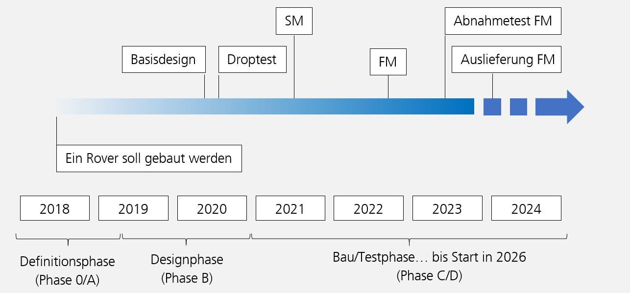
All structural components have now been delivered; the rover has been integrated and qualified. Installation on the MMX mother spacecraft in Japan will take place at the end of January/beginning of February 2024.
Timeline from definition to launch
SM stands for the simulation model, FM for the flight model.

